 |
|||
|
|
|||
|
Page Title:
Table 4-1. Hydraulic Pressures. |
|
||
| ||||||||||
|
|
 pressure indicated on the gage. Place the selector
lever in the reverse position and repeat the
procedure. Note the pressure indicated on the gage.
(c) If the pressures indicated are above 65
psi, and do not exceed normal pump pressure noted
in (1) above, the pressure in the clutch circuit is
normal.
(d) If the pressure is below 65 psi, check for
low oil level. restricted lines or passages, damaged
seal rings, defective or incorrectly adjusted selector
valve, defective pump. or excessive leaks in the disc
and drum assembly.
(e) When the engine is idling. and either
clutch is engaged. the clutch circuit pressure should
be 15 to 25 psi.
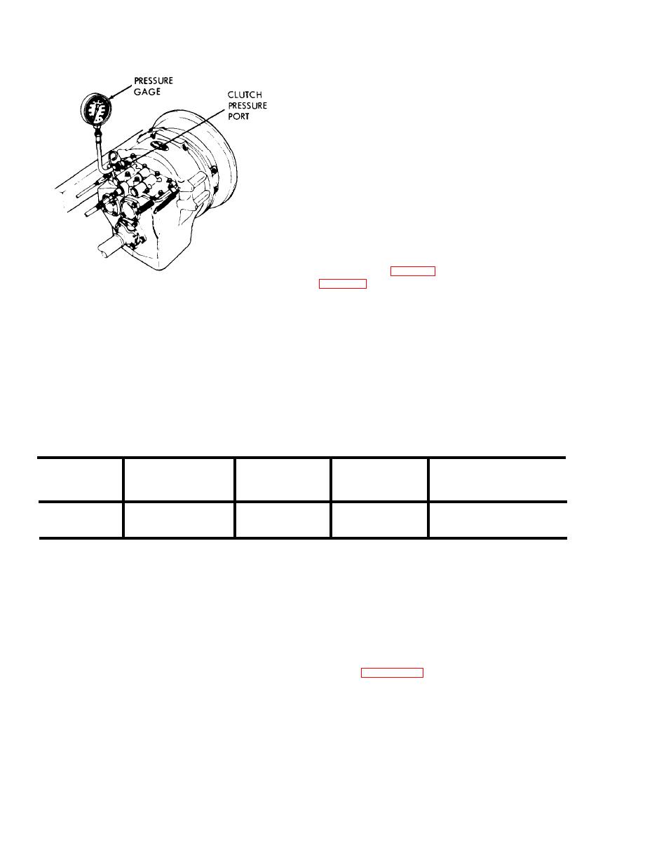
(4) Check the forward and reverse clutch
pressures with the wheels free running.
(a) Install pressure gages, calibrated to 300
psi, in the pump pressure port and the converter
pressure port (fig. 4-9) and clutch pressure port
(b) Raise the truck so that both drive
ME 3930-624-34/4-10
wheels are off the floor. Block the truck securely
Figure 4-10. Checking clutch pressure.
with both wheels free to rotate. Secure the inching
pedal up so the inching valve plunger cannot move.
(b) Start the engine and position the truck
Bring oil temperature to 200F.
against the wall. Apply both the parking brake and
(c) Run the engine at full governed speed
the foot brake-the drive wheels must be locked.
and check the pressures with the selector lever in
With the truck in this stalled condition, place the
both forward and reverse positions. The following
selector lever in the forward position and accelerate
cable indicates the normal pressures (in psi) at the
the engine momentarily to wide open throttle. DO
specified engine speeds:
not allow engine rpm to exceed 1500 rpm. Note the
Table 4-1. Hydraulic Pressures.
Forward
Reverse
Main line
Engine
clutch
clutch
Converter
(pump press)
rpm
Minimum Maximum Minimum Maximum
Minimum Maximum
Minimum Maximum
25
15
27
27
500
15
15
18
30
100
80
100
80
2000
125
105
65
80
Increase the pressure, if necessary. by adding a
(d) At a speed of 2000 rpm, release the
spacer between the spring and the hex head plug on
inching pedal. Clutch pressure should drop to zero
the lower right of the adapter. Cut off a small
in both forward and reverse positions.
portion of the spring (or remove washers. if any) to
(e) Disconnect the cooler return hose at the
return port on the left side of the adapter. Plug the
reduce pressure.
f. Regulating Valve Adjustment.
port. Install a 200 psi pressure gage in the hose.
With the clutch engaged and the oil sump tem-
(1) Remove the floor plate.
(2) Install a 0 to 160 psi pressure gage at the
perature at 120 to 170F, run the engine at
governed speed. The relief valve which protects the
pressure part on the top right of the control cover.
Refer to figure 4-11.
cooling oiI circuit must open at 65 psi to 100 psi. It
should open near 100 psi, and never under 6.5 psi,
4-8
|
|
Privacy Statement - Press Release - Copyright Information. - Contact Us |
