 |
|||
|
|
|||
|
Page Title:
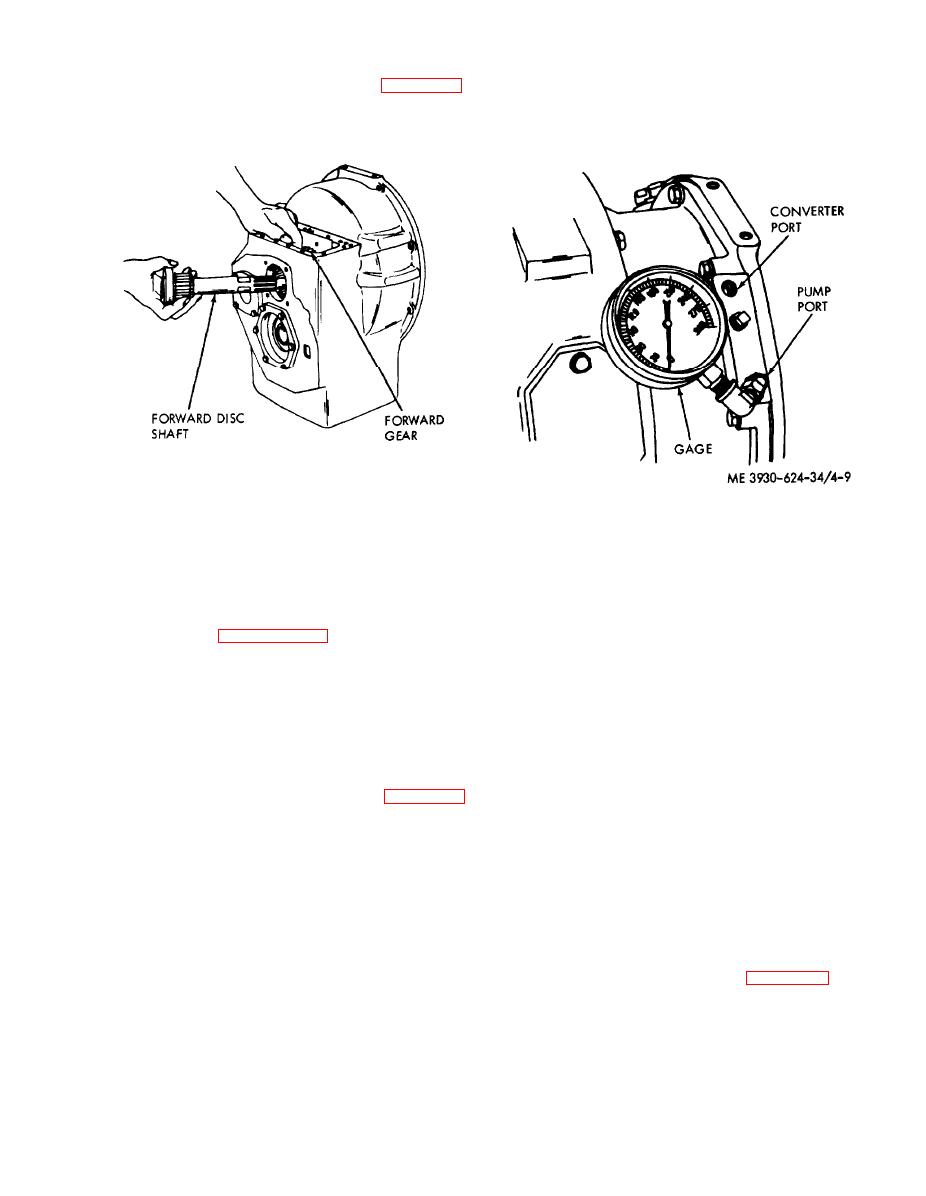
Check the pump pressure. See figure 4-9. |
|
||
| ||||||||||
|
|
 check the regulator valve spring and spool for free
(5) When installing the forward shaft (8),
operation or damage and check for restricted lines
forward gear (7) and reverse gear (13), ensure that
and passages. If the pump pressure is below 100
the snap rings (5, 9, 10 and 11) are properly in-
psi, check for low oil level, a faulty pump, excessive
stalled and completely seated. Refer to figure 4-8
line leakage, a f a u l t y r e g u l a t o r v a l v e , f a u l t y
for forward gear and shaft installation.
directional valve, or a clogged filter screen.
ME 3930-624-34/4-8
Figure 4-9. Checking pump and converter pressure.
Figure 3-8. Installing forward gear and shaft.
(2) Check the converter pressure. See figure 4-
(6) When installing the converter housing and
9.
disc drum to the transmission, be careful not to
(a) Install a pressure gage, calibrated to 300
damage the seal rings on the disc drum assembly.
psi, in the converter supply pressure port on the
e. Installation. Install the transmission in the
pump adapter.
(b) Leave the transmission in neutral and
truck. Refer to paragraph 2-9.
f. Testing. The transmission depends on correct
start the engine. Accelerate the engine to its full
operating pressures for efficient operation. The
governed speed (2200 rpm). Note the pressure
pressures to be checked are: pump pressure,
indicated on the pressure gage.
converter pressure, forward and reverse clutch
(c) If the converter pressure is 65 psi to 100
pressures (stalled and free running), inching
psi maximum, the converter is in normal operating
pressure, and clutch cooling oil pressure. The oil
condition. With the engine idling at 500 rpm, the
temperature should be 80 to 100F, except where
converter pressure should be between 10 psi and 30
otherwise specified.
psi.
(d) lf the converter pressure is above 100 psi
(1) Check the pump pressure. See figure 4-9.
(a) Install a pressure gage calibrated to 300
at 2200 rpm, check for excessive pump pressure,
psi. i n t h e p u m p p o r t o n t h e c o n v e r t e r p u m p
enlarged metering orifice, or restricted converter
adapter.
return passages. If the pressure is below 65 psi,
(b) Leave the transmission in neutral and
check for low oil level, clogged filter screen, faulty
start the engine. Accelerate the engine to its full
pump, or clogged converter orifice in pump
governed speed. Note the pressure indicated on the
collector ring.
pressure gage.
(3) Check the forward and reverse clutch
(c) If the pump pressure is between 100 psi
pressures at stall.
(a) Install a pressure gage, calibrated to 300
and 140 psi the pump is in normal operating
condition.
psi, in the clutch pressure port. See figure 4-10.
(d) If the pump pressure is over 150 psi,
4-7
|
|
Privacy Statement - Press Release - Copyright Information. - Contact Us |
