 |
|||
|
|
|||
|
Page Title:
Perform the following measurements and inspections on the connecting rod. |
|
||
| ||||||||||
|
|
 and installation tool. Take care not to spread the
rings more than necessary. Stagger the ring gaps
evenly around the piston so that no two are in line.
(2) Use the following procedure to install the
oil control rings (11).
(a) Place the stainless steel expander spacer
of the three piece ring in the nil groove with the
ends butted.
(b) Install the steel segment on top of the
expander spacer with the gap of the segment ap-
proximately 90 beyond the gap of the stainless
steel expander. Make certain the expander remains
butted.
(c) Install the second segment on the
bottom side of the expander spacer. Position the
segment gap approximately 90 from the expander
spacer gap in the opposite direction from which the
top segment has been positioned.
(d) Recheck the installation. The nil control
ring should be free to move in the groove. A slight
drag will be noticed due to the side sealing action of
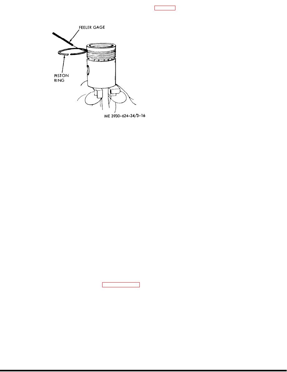
3-16. Checking ring-to-groove clearance.
the steel segments. Make sure the expander spacer
Figure
remains butted.
(4) Perform the following measurements and
(3) If the connecting rod bushing (9) is worn,
inspections on the connecting rod.
the old bushing may be pressed nut and a new
(a) Measure the outside diameter of the
bushing pressed in. Refer to the inspection
piston pin to determine the wear. The specified
procedure above to determine if the bushings are to
diameter of a new piston pin is 0.8591-0.8593 inch.
be replaced.
(b) The specified inside diameter of the
(4) If there is no wear between the piston (7)
connecting rod bushing is 0 . 8 5 9 3 - 0 . 8 5 9 6 i n c h .
a n d t h e p i n ( 6 ) , b u t wear exists between the
pin to bushing clearance is 0.0000-0.0005 inch.
bushing (9) and the pin, install a new bushing and
Clearance up to 0.0020 inch is permissible. If the
ream to fit a standard size pin.
clearance is close to or beyond this limit, replace the
(5) Use the following procedure to assemble
connecting rod bushing.
the connnecting rod (8) and piston.
(c) Inspect the connecting rod bearing
(a) Install one of the piston pin retaining
shells for scoring, chipping, corrosion, cracking, or
rings (5) in one end of the hole in the piston.
signs of over-heating. Discard the bearing shells if
(b) Immerse the piston in boiling water for
any of these conditions are apparent. The back of
approximately five minutes. Then insert the upper
the bearing shells should be inspected for bright
end of the connecting rod into the piston and insert
spots and discarded if any are found. This con-
the piston pin (6).
dition indicates they have been moving in their
(c) Install the other piston pin retaining
supports.
ring (5) at the opposite end of the piston pin.
(d) Inspect the bearing shells for wear. The
(6) When installing the pistons and con-
specified inside diameter of the bearing shells when
necting rods, b e s u r e t o p l a c e t h e m i n t h e i r
installed is 2.1239-2.1254 inches. This provides a
respective cylinders. The number on the bearing
running clearance of 0.0015-0.0040 inch. New
cap (3) should be opposite the camshaft side of the
bearing shells must be installed when this clearance
engine.
exceeds 0.000 inch.
(7) Place a ring compressor over the piston
rings. Make certain that the rings are wholly in
vvear and clearance. Refer to paragraph 3-17.
their grooves before tightening the compressor.
(5) If wear on the rod bushings or bearings
Tighten the compressor gradually. Pause to move
indicates that the rod is bent, replace the rod.
the compressor sideways to be sure the rings are
d. Reassembly and Installation.
free. Compress the rings as much as possible.
(1) If the rings have been removed from the
(8) Place the piston and connecting rod in its
piston. new rings must be installed. Refer to the
respective cylinder sleeve. The lower end of the
ring inspection procedure above to ensure that the
connecting rod should be aligned with the
rings meet with specifications. Install the rings (10.
3-19
|
|
Privacy Statement - Press Release - Copyright Information. - Contact Us |
