 |
|||
|
|
|||
|
|
|||
| ||||||||||
|
|
 KEY to fig 3-1:
until it Just contacts the stop pin. Then turn the
27. Needle bearing
1. Capscrew and lockwasher
screw in an additional 1 1/2 turns.
28. Venturi
2. Body
f. Installation. Install and adjust the carburetor
29. Float axle
3. Gasket
as directed in TM 10-3930-624-12.
30. Float
4. Gasket
31. Screw
5. Valve and seat
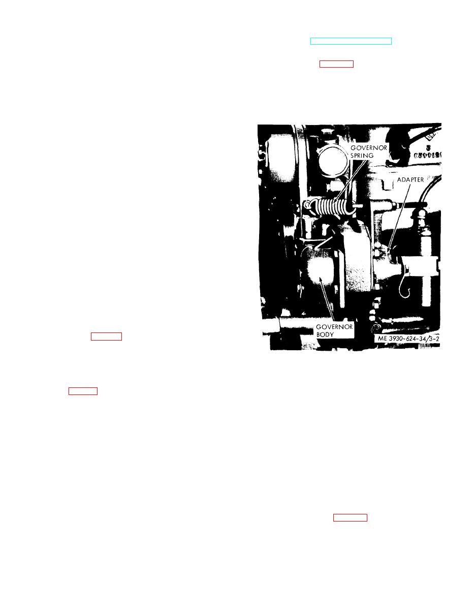
3-3. Governor
32. Plate
6. Washer
33. Plug
7. Jet
( 1 ) C l e a n the governor h o u s i n g a n d
34. Screw
8. Needle
35. Shaft and lever
9. Spring
surrounding area to keep dirt out of the governor
36. Screw
10. Plug
assembly.
37. Nut
11. Capscrew
(2) Remove the ignition coil from the governor
38. Clip
12. Plate
assembly.
39. Screw
13. Cotter pin
40. Bracket
14. Retainer
41. Retainer
15. Spring
42. Washer
10. Capscrew
43. Jet
17. Lever
44. Washt=r
18. Capscrew
45. Plug
19. Lever
46. Jet
20. Roll pin
47. Plug
21. Bushing
48. Washer
22. Washer
49. Jet
23. Washer
50. Washer
24. Seal
51. Jet
25. Screw
52. Body (fuel bowl)
26. Shaft
(6) Remove the plate (32) and the plug (33) SO
the shaft and lever (35) may be withdrawn from the
fuel bowl (52).
(7) Remove the clip (38) the bracket (40) and
the retainer(41).
(8) Remove jets (43, 46, 49 and 51).
c. Cleaning. Clean all metal parts in solvent.
Blow out all passages with compressed air. Make
certain that all carbon deposits have been removed
from the throttle bore and the ports.
d. Repair. Repair is limited to replacing parts
contained in a repair kit. The parts are as follows:
gasket (4,fig. 3-1), valve and seat (5), needle (8),
seal (24), float axle (29), plug (33), retainer (41)
and washers (6, 22, 42. 44, 48 and 50).
Figure 3-2. Governor.
e. Reassembly. Assemble in reverse order of
disassembly. observing the following :
(3) Remove the governor spring from the
(1) When installing the idle adjustment needle
adjusting screws and disconnect the governor lever
(8, fig. 3-) and friction spring (9) into the front of
from the governor control rod.
the body, do not overtighten. The seat may be
(4) Remove the stud nut and the two cap-
damaged. Seat needle lightly, then back the ad-
screws from the flywheel housing. Lift the governor
justment needle out 1 turns for preliminary
body away from the gear housing. In some in-
adjustment.
stances the governor weights, shaft and drive gear
(2) Check for the correct float level. Invert the
will remain in the gear housing.
throttle body. Measure from the machined surface
(5) Slide the thrust bearing and sleeve off the
of the body to the top side of the float bodies at the
weight assembly shaft and work the drive gear free
highest point. This dimension should be 1 5 /32
1 / 32 in. To increase or decrease the distance
from the adapter.
(6) Remove the two capscrews and lock-
between the float body and the machined surface,
washers which attach the adapter to the front plate
use a long-nosed pliers and bend the lever close to
and gear housing. Remove the adapter and thrust
the float body.
vvasher. Remove the governor assembly.
(3) After fuel bowl and throttle body have
been assembled, perform preliminary adjustment of
(1) Disassemble the adapter by removing the
the idle speed. Turn the throttle stop screw (25) in
3-3
|
|
Privacy Statement - Press Release - Copyright Information. - Contact Us |
