 |
|||
|
|
|||
|
|
|||
| ||||||||||
|
|
 Caution: Be sure all hydraulic lines.
electrical wiring, fuel lines, and mechanical
linkages are disconnected and tagged before
trying to remove the engine.
(17) Using a suitable hoist. raise the engine
high enough to cIear the engine supports. Move the
engine toward the war to free the transmission from
the drive shaft slip joint. Raise and remove the
engine and transmission from the truck.
b. lnstallation.
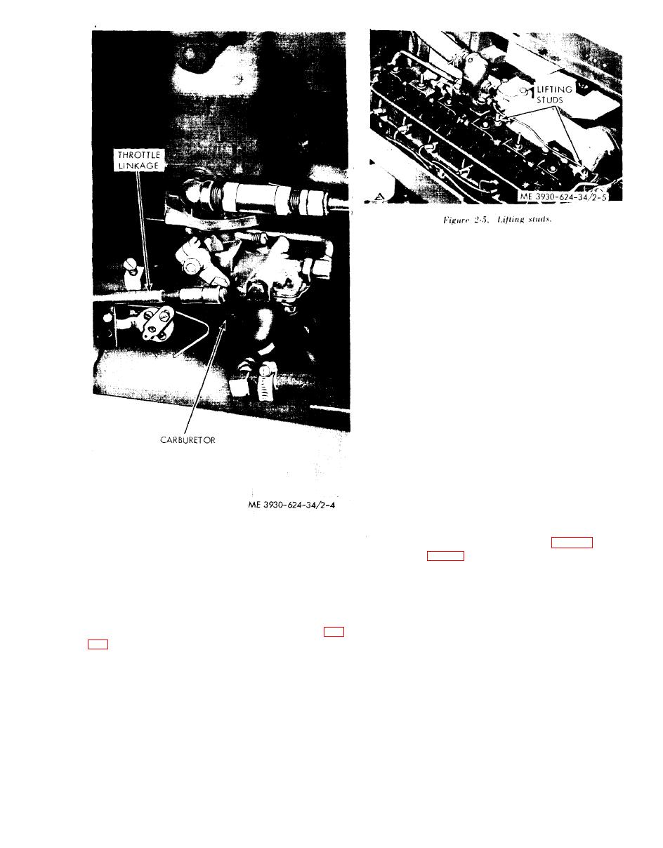
(1) Attach a lifting sling to the lifting studs on
the cylinder head. Using a suitable sling. slowly
lower the engine and transmission onto the truck
frame .
(2) Have an assistant line up the drive shaft
slip joint so that it will enter the output shaft of the
transmission without damage during installation.
(3) With the, engine correctly alined in the
truck frame and positioned on the rubber mounts.
install the mounting capscrews, Washers. and nuts.
Tighten the nuts to a torque of 60 ft lbs and removed
the hoist and sling.
(4) Connect the exhaust pipe, using a new
gasket.
Figure 2-4. Throttle linkage.
(5) Connect the throttle linkage (fig. 2-4) and
(14) Disconnect the exhaust pipe from the
shift Iinkage (fig. 2-3), and make the initial ad-
justments at this time. Final adjustment can be
manifold.
made after installation is complete.
(15). Removed the nuts, washers, and capscrews
(6) Conncted the fuel supply lines and open the
securing the front and rear engine mounts to the
shutoff valve.
truck frame.
(7) Install the wiring harness.
(16) Remove the rocker arm cover. Install
(8) Clamp the hydraulic hose along the oil
internally threaded eyebolts on the lifting studs (fig.
pan and connect the lines to the hydraulic pump.
2-9
|
|
Privacy Statement - Press Release - Copyright Information. - Contact Us |
