 |
|||
|
|
|||
|
Page Title:
Figure 4-35. Unlocking instrument panel from lock pins. |
|
||
| ||||||||||
|
|
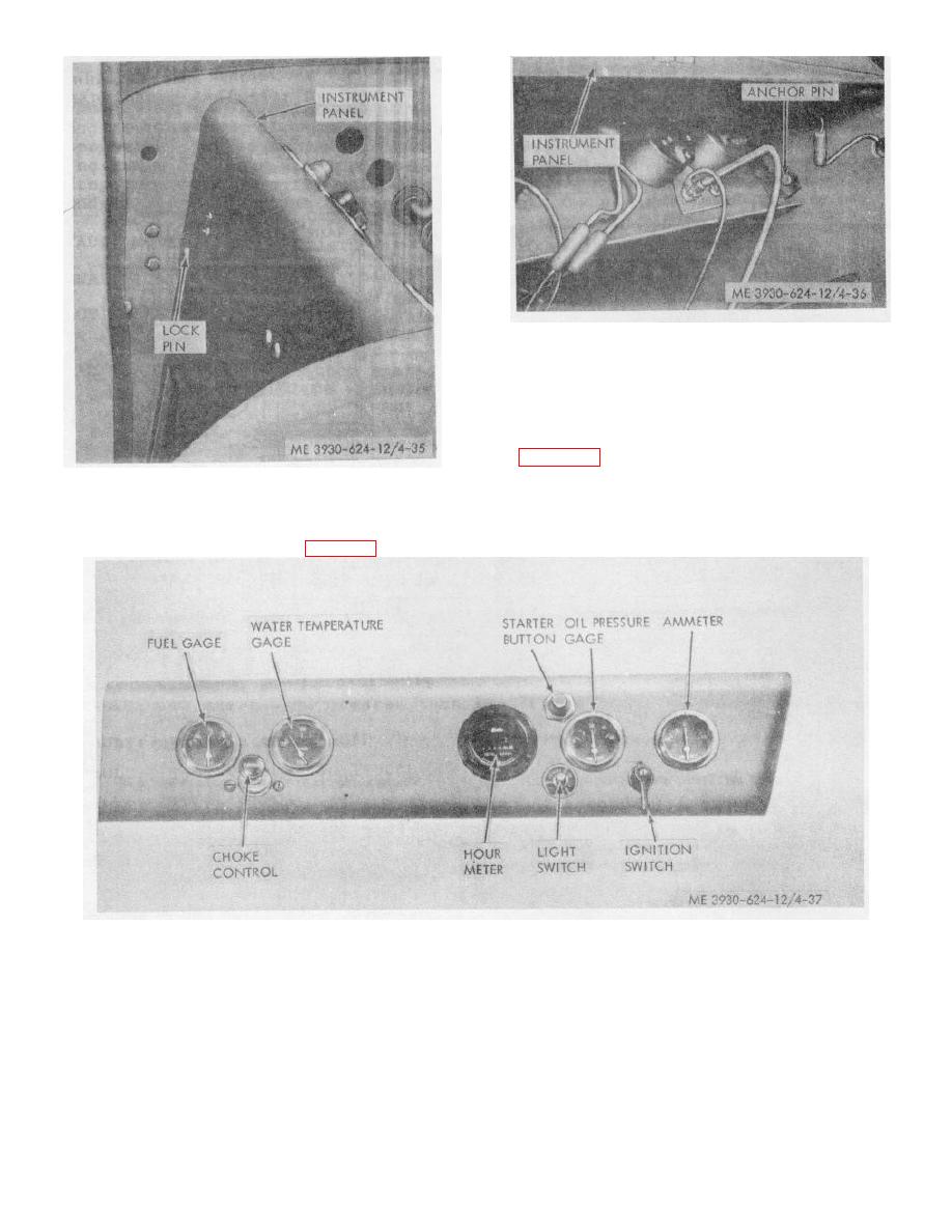 Figure 4-36. Instrument panel anchor pins.
Caution: Before removing anything from the
instrument panel be sure to tag all electrical leads to
ensure their correct installation.
(4) Remove any of the units from the
instrument panel as necessary for replacement. Refer
to figure 4-37.
Figure 4-35. Unlocking instrument panel from lock pins.
(3) Swing the instrument panel back and
Sown to release it from the anchors on the side panels,
and lift the assembly from the truck (fig. 4-36)
Figure 4-37. Instrument panel gages, meters, and switches.
b. Cleaning and Inspection.
(4) Inspect the switches for binding operation,
damaged terminals, signs of overheating, damaged
(1) Clean the meters, gages, and switches
threads or other defects; replace faulty switches.
with a cloth dampened with a cleaning solvent. Take
(5) Inspect the instrument panel for cracks,
care to prevent the solvent from entering the parts.
dents, distortion, and other damage; replace damaged
(2) Clean all other parts with solvent and dry
instrument panel.
thoroughly.
(3) Inspect meters and gages for cracked
glass, illegible dial faces, damaged terminals, and other
damage.
4-35
|
|
Privacy Statement - Press Release - Copyright Information. - Contact Us |
