 |
|||
|
|
|||
|
|
|||
| ||||||||||
|
|
 TM 10-3930-623-34
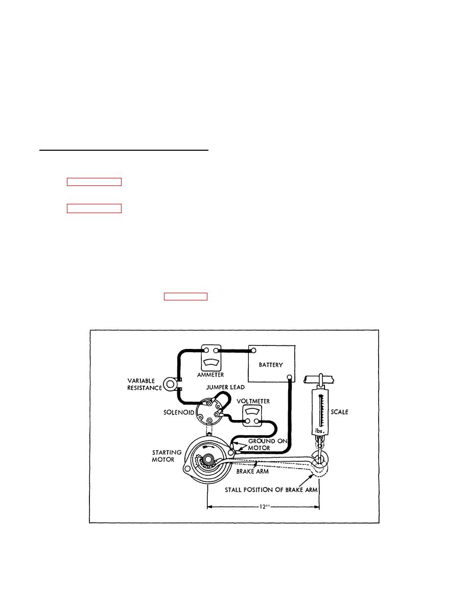
indicated on the scale and compensate for length of the
carbonized (burnt) paths caused by current leakage.
brake arm. Corrected torque value shall be 10.5 foot-
Discard defective cap assembly.
pounds.
2. Examine metal inserts in cap terminals for
burning or pitting. Discard cap assembly if severe
NOTE
burning or pitting is noticed.
The true torque value is obtained by
multiplying the scale reading by the
3. Examine rotor (17) for cracked or chipped spots
length of the brake arm in inches and
or burned tip.
dividing by 12.
brake arm x scale reading = torque in foot-pounds
4. Check rotor segment for excessive burning. If
12
only end of rotor segment is burned, operation of rotor is
not impaired. Discard rotor and cap assembly if burning
3. If low torque and high current are obtained in
is found on top portion of rotor segment or on plastic.
test, repeat paragraph 7-30, step 4.
5. Examine breaker plate (26) for damage.
4. If low torque and low current are obtained in
test, repeat paragraph 7-30, step 5.
6. Examine capacitor (20) for broken leads, frayed
insulators, or loose and corroded terminal clips. Be sure
5. If severe arcing is noticed during test, check
capacitor has secure ground connections.
tension of brush spring. Examine brushes for wear and
contact with commutator, and check soldered
7. Check condition of capacitor with a suitable
connections of armature windings at commutator.
tester. Replace capacitor if test indicates grounds or if
capacity of capacitor exceeds 0.20 microfarads, plus or
minus 10%.
7-32. DISTRIBUTOR INSPECTION.
8. Examine contact point set (18) for excessive
1. Examine cap and shield (10, figure 4-19) for
pitting. Discard set if buildup on stationary contact is
cracks and chipped spots.
Check inside of cap
greater than 0.020 inch.
assembly for
Figure 7-6. Starter Stall Current and Torque Test Setup
7-12
|
|
Privacy Statement - Press Release - Copyright Information. - Contact Us |
