 |
|||
|
|
|||
|
|
|||
| ||||||||||
|
|
 TM 10-3930-623-34
3. Lubricate packing (58) with automotive and
6-68. ADJUSTER PLUG DISASSEMBLY.
artillery grease, MIL-G-10924, and install on adjuster
1. Remove thrust bearing retainer (57, figure 4-32)
plug. Assemble large thrust bearing race (53), thrust
with a screwdriver, being careful not to score the needle
bearing (54), small thrust bearing race (55), and thrust
bearing bore, and discard.
Remove thrust bearing
bearing spacer (56) on adjuster plug. Press new bearing
spacer (56), thrust bearing (54) and thrust bearing races
retainer (57) into needle bearing bore, using thrust
(53 and 55).
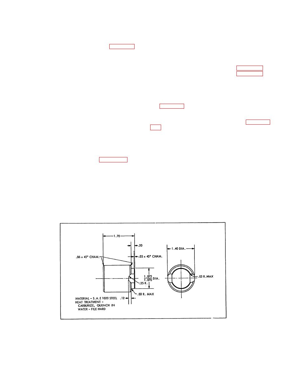
bearing retainer installer, as shown in figure 6-11. If
necessary, make installer locally, using figure 6-11 for
2. Remove adjuster plug packing (58) and discard.
guidance.
3. Remove stub shaft seal retaining ring (50), with
6-70. ADJUSTER PLUG INSTALLATION.
snap ring pliers, and remove stub shaft dust seal (47).
1. Place tool to protect seal over end of stub shaft
4. Remove stub shaft oil seal (48) by prying out
(76, figure 4-32).
with screwdriver and discard.
2. Install adjuster plug assembly in gear housing.
5. Inspect adjuster plug needle bearing (51), and if
Adjust thrust bearing preload according to paragraph
rollers are broken or pitted, remove needle bearing from
adjuster plug by pressing from thrust bearing end using
piloted driver. Discard bearing.
6-71. STEERING GEAR VALVE. The complete valve
in each steering gear is a precision unit with selective
fitted parts and is hydraulically balanced at assembly.
6-69. ADJUSTER PLUG ASSEMBLY.
Only those parts which are service items are replaceable
1. Assemble needle bearing (51, figure 4-32) by
and interchangeable.
No other valve parts are
pressing from thrust bearing end of adjuster plug (52)
individually interchangeable.
Replacement of any
against identification end of bearing. End of bearing is to
nonserviceable valve part requires that complete rotary
be flush with bottom surface of stub shaft seal (48) bore.
valve assembly be replaced. Do not disassemble the
valve unless necessary since this may result in
2. Lubricate new stub shaft seal with OE-10 engine
damaging the assembly.
If valve spool dampener
oil and install far enough to provide clearance for dust
packing requires replacement, remove valve spool only,
seal (47) and retaining ring (50). Lubricate new dust
replacing packing, and reinstall spool immediately. Do
seal with engine oil and install with rubber surface
not disassemble further. Proceed as follows:
outward. Install retaining ring (50), making certain that
the ring is properly seated.
Figure 6-11. Steering Gear Thrust Bearing Retainer Installer Tool Details
6-18
|
|
Privacy Statement - Press Release - Copyright Information. - Contact Us |
