 |
|||
|
|
|||
|
|
|||
| ||||||||||
|
|
 TM 10-3930-623-34
2. Disconnect the power steering hose at the
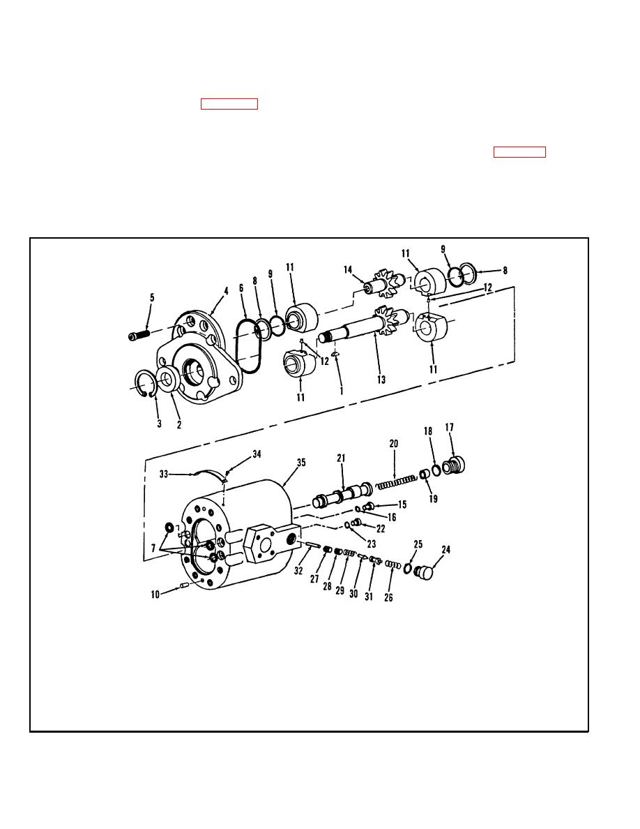
4-35. HYDRAULIC OIL PUMP.
pump, remove nuts (25), washers (26) and take pump
and gasket (27) from engine. Discard gasket.
removed from above, drain cooling system and remove
radiator first, for access to pump. Then remove pump as
4-37. DISASSEMBLY.
follows:
1. Remove woodruff key (1, figure 4-7) from slot in
1. Remove the flange halves (13 and 20),
pump drive gearshaft (13).
disconnecting the pump pressure and suction lines at
the pump. If fluid continues to flow from either line, raise
2. Remove retaining ring (3), cap screw (5), seal
the end of that line above the level of the top of the
(2) and mounting flange cover (4).
hydraulic tank.
1.
Woodruff Key
10.
Pin
19.
Spring Seat
27.
Lock Screw
2.
Oil Seal
11.
Shaft Bushing
20.
Spring
28.
Adjusting Screw
3.
Retainer Ring
12.
Pin
21.
Priority Valve Spool
29.
Spring
4.
Pump Mounting Flange
13.
Drive Gear
22.
Passage Plug
30.
Plunger Cone
5.
Screw
14.
Idler Gear
23.
Preform Packing
31.
Relief Valve Spool
6.
Preform Packing
15.
Passage Plug
24.
Steering Pressure
32.
Roll Pin
7.
Preform Packing
16.
Preform Packing
Valve Plug
33.
Identification Plate
8.
Back-Up Ring
17.
Priority Valve Plug
25. Preform Packing
34.
Drive Screw
9.
Preform Packing
18.
Preform Packing
26. Spring
35.
Pump Body
Figure 4-7. Hydraulic Pump Assembly, Exploded View
4-9
|
|
Privacy Statement - Press Release - Copyright Information. - Contact Us |
