 |
|||
|
|
|||
|
|
|||
| ||||||||||
|
|
 TM 10-3930-623-34
1-43. The oil pressure sending unit is connected into the
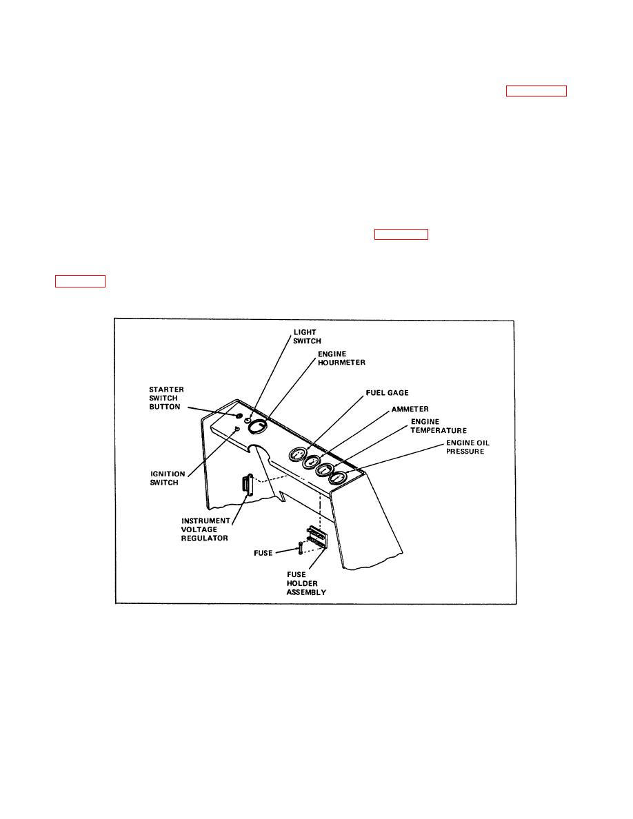
1-45. INSTRUMENT PANEL (See figure 1-12). The
pressure side of the lubricating oil system. This unit
instrument panel assembly incorporates the usual
contains a coil, the resistance of which varies with
standard instruments in a compact group. The engine
pressure. Actuating current to the instrument passes
operation hourmeter is used to determine when periodic
through this resistance coil which varies the current, and
service operations are due. in addition to controlling the
thus the indication, in proportion to the pressure on the
ignition system, the ignition switch energizes the
sending unit.
instruments, and the starter circuit up to the starter
button. The light switch operates the spot light and
taillight.
1-44. The water temperature sending unit is threaded
1-46. The fuses in the fuse holder protect the various
into the engine cylinder head to sense and respond to
electrical circuits of the truck. Refer to the wiring
engine coolant temperature.
This unit contains a
diagram (figure 1-11) for identification of each fuse.
temperature sensitive resistance coil which regulates the
flow of actuating current to the engine temperature gage
1-47. The instrument voltage regulator is a small voltage
in
to
engine
coolant
temperature
divider which reduces system voltage to six volts for
(see figure 1-2).
instrument power.
Figure 1-12. Instrument Panel
1-13/14
|
|
Privacy Statement - Press Release - Copyright Information. - Contact Us |
