 |
|||
|
|
|||
|
|
|||
| ||||||||||
|
|
 TM 10-3930-623-34
1-16. The distributor times the occurrence of the ignition
1-19. The flow divider (priority) valve directs the pump
spark in relation to the engine by means of a set of
output to both the power steering system and the control
breaker points operated by an engine-driven cam.
valve assembly inlet port. A relief valve in the flow
Variations in timing under changing speed are
divider valve limits hydraulic pressure in the power
accomplished through a centrifugally operated spark
steering system. This relief valve cracks open at 700 psi
advance mechanism in the distributor. The timed high
and is fully open at 1050 psi.
voltage impulses are fed through the center terminal of
the distributor cap to the rotor inside. The rotor then
1-20. The control valve assembly is a two-spool fluid
directs the high voltage to each spark plug wire
control valve with a control handle for each spool. The
(arranged from cap to spark plugs in proper engine firing
inboard control handle and spool control the raising and
order) in sequence, to spark each spark plug at the
lowering of the forks by applying or releasing hydraulic
proper time.
pressure to the hoist cylinder. The outboard control
handle and spool control tilting of the upright carriage.
1-17. HYDRAULIC PUMP. Hydraulic pressure for
Each control handle has two actuating positions with a
steering, hoisting, and tilting of the uprights is supplied
center neutral position. A pilot operated relief valve
by an engine-driven hydraulic pump. This pump is
limits system pressure to 1500 psi. The hoist cylinder is
mounted at the left rear side of the engine, driven by a
a two-stage single-acting unit, raised by applying fluid
gear which engages the camshaft timing gear. The
pressure, and lowered by releasing pressure to permit
pump is a gear type positive displacement pump.
gravity return of the elevated parts. The tilt cylinders are
double-acting cylinders.
1-18. UPRIGHT CARRIAGE AND FORK ASSEMBLY
Using
1-21. POWER STEERING GEAR. The power steering
HYDRAULIC SYSTEM (See figure 1-4).
pressure from the engine-driven hydraulic pump, this
gear unit is basically a Saginaw recirculating ball
system controls raising of the forks and fore and aft
steering gear to which has been added a torque
tilting of the uprights. The control valve assembly
sensitive valving arrangement, and in which the ball nut
permits the operator to direct pressure to the hoist
has been redesigned to act as a hydraulic piston. The
cylinder for raising the forks, or to the tilt cylinders to
valve (see figure 1-6) is an open-center rotary three-way
adjust the angle of the uprights and forks.
valve, with a grooved spool to
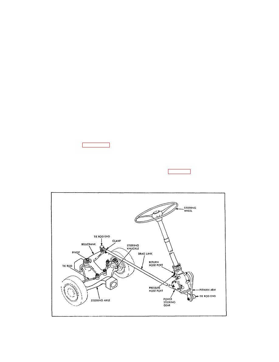
Figure 1-5. Steering System Arrangement
1-5
|
|
Privacy Statement - Press Release - Copyright Information. - Contact Us |
