 |
|||
|
|
|||
|
Page Title:
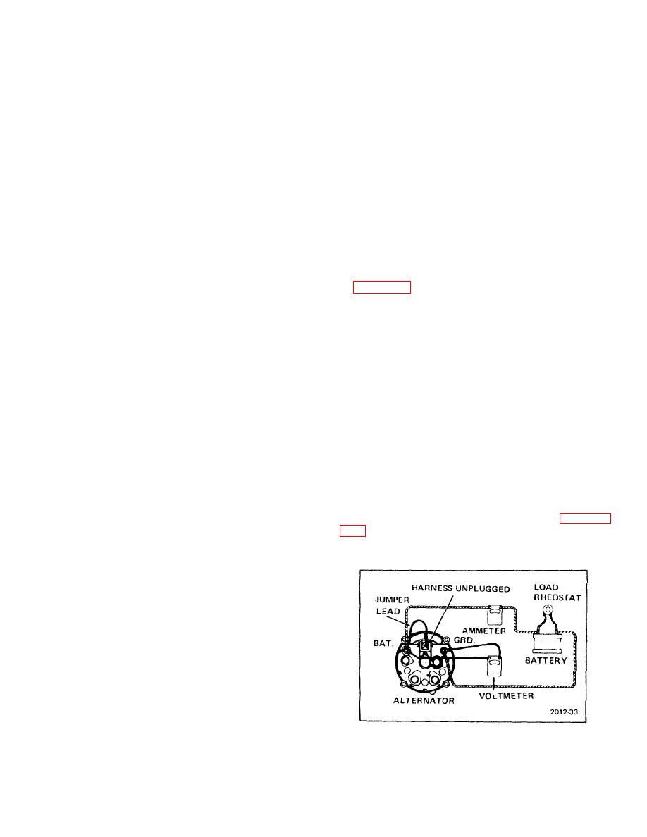
Figure 5-12. Alternator Test Setup |
|
||
| ||||||||||
|
|
 TM 10-3930-623-12
b. Inspect alternator for cracked housing, bent
shaft, or damaged drive pulley. Turn shaft by hand; it
should rotate freely with no catching or binding. Replace
or repair damaged alternator.
c. Alternator Test.
(1) Connect assembled alternator as shown
in figure 5-12. Make sure negative terminal is connected
to ground. Adjust load rheostat to obtain specified
output of 14 volts. Check amperage at 2000 alternator
rpm or 1000 engine rpm (cold); it should be 21 amperes.
Check amperage at 5000 alternator rpm or 2500 engine
rpm (cold); it should be 30 amperes. Operate alternator
until it is at operating temperature.
Check output
amperage; it should be 32 amperes.
(2) If output is not as specified, replace
d. Alternator Installation.
(1) Position alternator on mounting bracket;
secure with mounting bolt.
(2) Loosely attach alternator to adjusting strap
with cap screw. Move alternator down and slip belts
over pulley. Adjust belt tension as directed in paragraph
Connect alternator as
Figure 5-12. Alternator Test Setup
5-11
|
|
Privacy Statement - Press Release - Copyright Information. - Contact Us |
