 |
|||
|
|
|||
|
|
|||
| ||||||||||
|
|
 TM 10-3930-623-12
3. If timing mark does not appear centered in hole,
5. Tighten distributor clamp bolt, reinstall spark plug
loosen distributor clamp bolt just enough to permit
and plug wire.
rotation by hand of the entire distributor with a slight
drag.
While observing timing mark with light, turn
5-31. DISTRIBUTOR MAINTENANCE.
distributor in its mounting hole until timing mark is
centered in hole.
1. Contact Point Cleaning. Dirty contact points should
be dressed with a few strokes of a clean, fine-cut contact
4.
Retighten distributor clamp bolt, and recheck
file. The file should not be used for other metals and
timing.
should not be allowed to become greasy or dirty. Never
use emery cloth to clean contact points.
Contact
5-30.
STATIC TIMING METHOD.
The following
surfaces, after considerable use, may not appear bright
instructions presume the timing needs only minor
and smooth, but this is not necessarily an indication that
adjustment. If the distributor has been removed from the
they are not functioning satisfactorily. Do not attempt to
engine, refer to the instructions for reinstallation of the
remove all roughness nor dress the point surfaces down
distributor in Section 6; otherwise, proceed as follows:
smooth; merely remove scale or dirt. Badly burned or
pitted contact points should be replaced and the cause
1. Remove spark plug from number 1 cylinder. With
of trouble determined so it can be eliminated. High
ignition switch OFF, seal plug hole with thumb, and
resistance or loose connections in the condenser circuit,
crank engine (or turn it slowly by turning the fan by hand)
oil or foreign materials on the contact surfaces, improper
until pressure can be felt at plug hole. This pressure
point adjustment or high voltages may cause oxidized
indicates piston is coming up on compression stroke.
contact points. Check for these conditions where burned
contacts are experienced. An out-of-balance condition
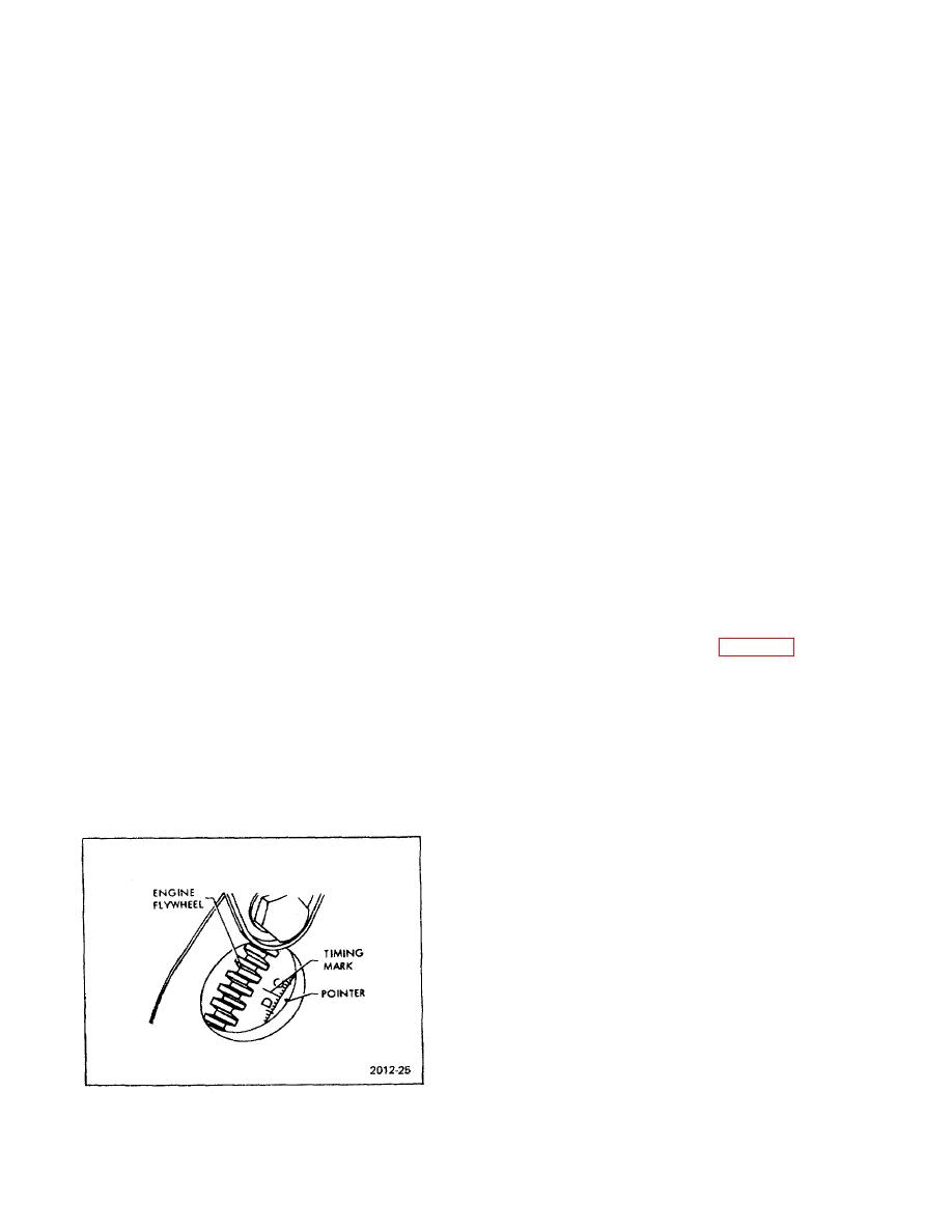
2. Continue to turn engine slowly until timing mark is
in the ignition system, often the result of too much or too
seen through hole in flywheel housing as shown in figure
little condenser capacity, is indicated where point pitting
54. Center mark in hole.
is encountered.
3. Remove distributor cap, loosen distributor clamp
2. Contact Point Replacement.
bolt, and turn distributor counterclockwise until breaker
points are definitely closed.
a. Release distributor cap hold-down
screws,
remove cap and place it out of work area.
4. Turn ignition switch ON. Turn distributor body
clockwise slowly until exact position is reached at which
b. Remove rotor.
breaker points separate. Do not over travel beyond this
point. Reaching this position will be indicated by one or
c. Disconnect primary and condenser lead wires
more of the following:
from contact point terminal (see figure 5-5).
a. A slight spark can be seen at the points if
d. Remove contact set attaching screw, lift cont act
distributor cap is removed.
point set from breaker plate.
b. The ammeter reading (discharge) will decrease
e. Clean breaker plate of oil smudge and dirt.
suddenly.
f. Place new contact point assembly in position on
c. With distributor cap installed and spark plug end
breaker plate, install attaching screw.
of number one plug wire held about 1/8 inch from
cylinder head, a spark will be seen.
CAUTION
Carefully wipe protective film from
point set prior to installation.
NOTE
Pilot on contact set must engage
matching hole in breaker plate.
g. Connect primary and condenser lead wires to
terminal on contact point set.
h. Check and adjust points for proper alignment
and breaker arm spring tension. Use an aligning tool to
bend stationary contact support if points need alignment.
Figure 5-4. Flywheel Timing Marks
5-5
|
|
Privacy Statement - Press Release - Copyright Information. - Contact Us |
