 |
|||
|
|
|||
|
Page Title:
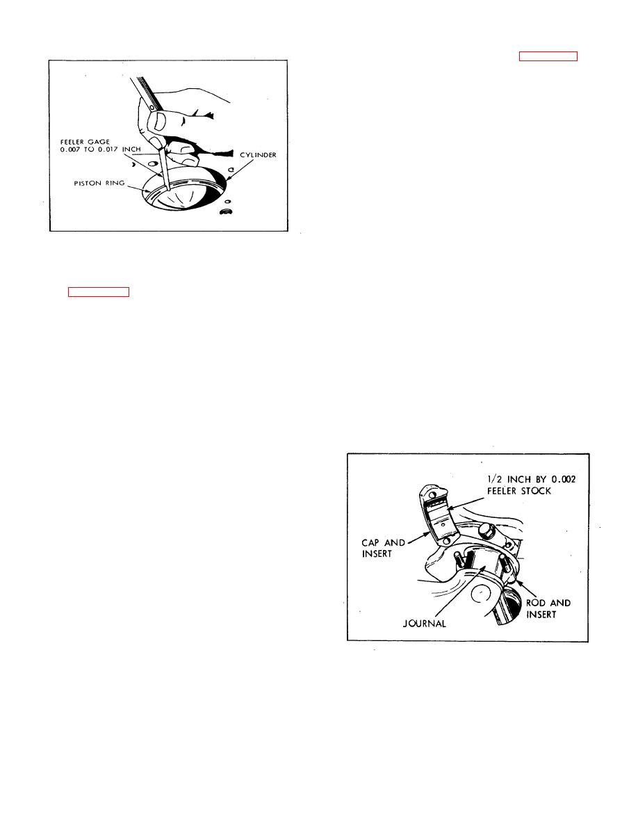
Figure 6-36. Measuring Ring End Gap |
|
||
| ||||||||||
|
|
 rod bearing calf and crankshaft journal (Figure 6-37).
Install connecting rod bearing cap and tighten nuts to 39
foot pounds torque. Try to rotate crankshaft one full turn
by hand. If drag is felt, the clearance is correct. If the (
crankshaft turns freely, it will be necessary to measure
crankshaft journal for taper or out of round. If taper or
out of round exceeds 0.0015 inch, replace crankshaft.
i. Installation.
(1) It is important to remove glaze on cylinder
bore to assure quick seating of piston rings.
(a) Cover crankshaft journals with clean cloth to
prevent dirt and abrasives, from getting on crankshaft.
(b) Surface hone cylinder bores with glaze breaker
to break glaze and produce dull finish in bore. Clean
glaze breaker between use in each cylinder bore to
reduce amount of loose abrasives released in bore.
Figure 6-36. Measuring Ring End Gap
(c) Clean cylinder bores thoroughly with clean oiled
rag, to pick up any abrasive that might be left in bore.
bore (use a piston to straighten the ring in the cylinder)
Follow this with clean cloth to assure that walls are
measure the gap between the ring ends with a feeler
clean.
gauge (Figure 6-36). The ring gap for all rings is 0.015
(2) Install oil rings and compression rings on
to 0.020 inch. If the gap is less than specified, remove
piston with ring expander tool Start with the lowest ring
the ring and dress end with a fine-cut mill file until correct
first. Make sure that tapered side of compression ring is
clearance is obtained.
up. Make sure that the ring gaps are equally spaced
(3) Measure side clearance of piston rings in
about circumference of the piston, not in vertical
the grooves with feeler gauge. Gap should be 0.0035 to
alignment.
0.005 inch for top compression ring. Scraper and oil ring
(3) Oil cylinder wall and generously coat
gap is 0.0015 to 0.003 inch. If clearance is less than
piston and rings with OE (lubricating oil, internal
specifications, remove ring from piston and rub the ring
combustion engine).
lightly on piece of fine emery cloth (all on flat surface)
(4) Install ring compressor on piston and
until proper clearance is obtained.
compress rings into grooves. Tap compressor lightly
g. Connecting rod alignment.
around circumference of piston to allow rings to seat
(1) Install piston pin in connecting rod and
evenly in grooves.
place connecting rod, with sleeve bearings, on aligning
fixture. Install connecting rod bearing cap on connecting
rod.
(2) Pin should touch measuring bar on
aligning fixture at both ends. Straighten bent or twisted
connecting rods. Maximum bend or twist may not
exceed 0.inch over 4 inch spread of length of the
connecting rod.
h. Connecting rod bearing installation.
(1) Connecting rod bearings that are scored,
burned, or damaged must be replaced by new ones.
Replacement bearings require no reaming or fitting.
(2) Install the piston with connecting rod and
with upper half of connecting rod bearing installed, but
without piston rings, in the cylinder bore. Coat a piece of
0.002 inch feeler stock, approximately 1/2 inch wide and
1 inch
Figure 6-37. Measuring Rod Bearing Clearance
108
|
|
Privacy Statement - Press Release - Copyright Information. - Contact Us |
