 |
|||
|
|
|||
|
|
|||
| ||||||||||
|
|
 (2) Remove nuts, washers and screws attaching
(2) Loosen locknut on brakeshoe stop screw, tighten
lever to truck body. Take brake lever and' linkage from
stop screw until both brakeshoes grip drum, then slack it
truck.
off just enough to release drum. Tighten locknut.
b. Installation. Reverse a. above.
(3) Set lever to position in which brakes are applied
and turn adjusting knob clockwise until snug. Release
c. Adjustment. Make overall adjustment of parking
brakes and tighten knob further until a firm pull is
brake system as follows: (1) Turn. adjusting knob on
required to draw lever over center and brake application
lever
handle
full counterclockwise to slack off
is adequate to hold truck.
adjustment.
6-20. PEDAL AND LINKAGE.
a. Removal.
(1) Remove five screws, nuts and washers, and
remove floorboard.
(2) Remove pedal nuts and washers, and pedals
cylinder clevis. Do not unscrew clevis from master
cylinder unnecessarily to avoid disturbing pedal
adjustment excessively.
(3) Remove inching valve adjustment screw and
spring, brake lever mounting screws and bearings, and
brake lever.
b. Installation.
(1) Reverse a. above.
(2) Perform procedure in paragraph 6-23b. (4).
(3) With drive wheels raised off floor and forward
clutch engaged, turn adjusting nut, or add washers, until
no movement of the inching spool is detected at all
engine speeds.
6-21. BRAKE SHOES (PARKING BRAKE).
a. Adjustment.
(1) Fully release parking brake lever and turn
adjustment knob at top of brake handle counterclockwise
to slack off linkage adjustment.
(2) Loosen nut on brake shoe stop screw (Figure 6-
8) and adjust screw until lining of both shoes contacts
brake drum.
(3) Back off brake shoe stop screw two turns and
tighten nut to hold adjustment.
(4) Apply parking brakes and tighten adjustment
knob snugly, to the extent a firm push is required to
release the parking brake.
b. Removal.
(1) Remove twelve capscrews and remove as much of
propeller shaft as necessary to get access to nut holding
on parking brake drum.
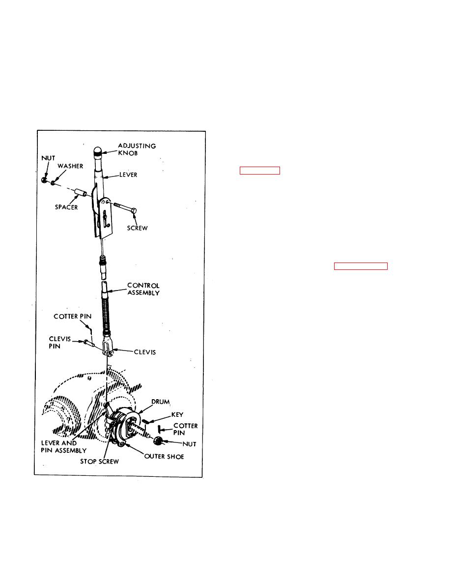
Figure
6-6.
Handbrake,
Partly
Exploded
View
59
|
|
Privacy Statement - Press Release - Copyright Information. - Contact Us |
