 |
|||
|
|
|||
|
|
|||
| ||||||||||
|
|
 5-62. STARTING AND CHARGING SYSTEM.
5-63.
STARTING MOTOR INSPECTION AND
CLEANING.
Remove the commutator end cover.
Inspect the commutator for dirty condition, roughness,
high spots and high mica. If the commutator is dirty,
remove the brushes
and
carefully
clean
the
commutator with a commutator stone. Blow out dust
with compressed air and replace brushes in their original
brush holders. If the commutator is rough, out-of-round
or has high mica, replace the starting motor.
5-64.
STARTING MOTOR BRUSH INSPECTION.
Inspect brushes and replace if they are excessively worn
or oil soaked. Brush spring tension should be checked
with a spring scale. To check the tension of brush
spring, hook scale 'under the brush spring near the brush
and pull on a line parallel with the side of the brush.
Take the reading just as the spring leaves the brush.
Spring tension should be 35 ounces. If the spring
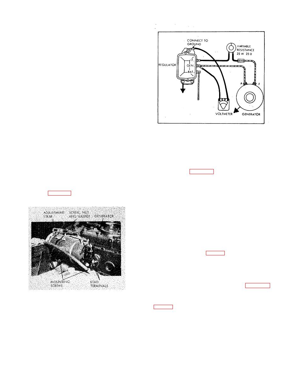
Figure 5-7. Cutout Relay Test Setup
tension is too low, there will be a loss of efficiency due to
poor brush contact.
If tension is too great, the
c. Remove mounting screws at underside of
commutator and brushes will wear excessively and have
generator. Disengage generator from fan belt and
short life. It is, therefore, important the brush spring
remove generator.
tension be kept within the limits specified. To adjust
spring tension, twist the spring at holder with a long-
5-66. GENERATOR INSTALLATION.
nosed pliers.
5-65. GENERATOR REMOVAL.
belt to 1/2-inch deflection under thumb pressure, midway
in long span.
a. Disconnect and tag leads at generator lead
b. Repolarize generator, after all electrical
terminals. (See figure 5-6).
connections have been made, by briefly shorting
b. Remove adjustment screw, nut and washer at
together the BAT and GEN terminals of the generator
strap.
regulator with a jumper wire, or a screwdriver blade, just
long enough to cause a spark.
5-67. GENERATOR REGULATOR TESTING.
a. Cutout Relay Test.
(1) Disconnect lead at regulator F terminal
and connect 0.25 ohm 25 watt variable resistor in series
with F terminal and lead (Fig. 5-7).
(2) Connect voltmeter from GEN terminal to
ground on frame. Remove regulator cover and operate
engine at fast idle.
(3) Increase field resistance until cutout relay
opens, then decrease it until points close. Observe
voltage at which points close (refer to Table 2-1).
Perform step b. below next.
Figure 5-6. Generator, Installed
b. Voltage Regulator Test.
(1) Disconnect battery lead from BAT terminal
more) watt resistor between the BAT terminal and
ground on frame.
35
|
|
Privacy Statement - Press Release - Copyright Information. - Contact Us |
