 |
|||
|
|
|||
|
Page Title:
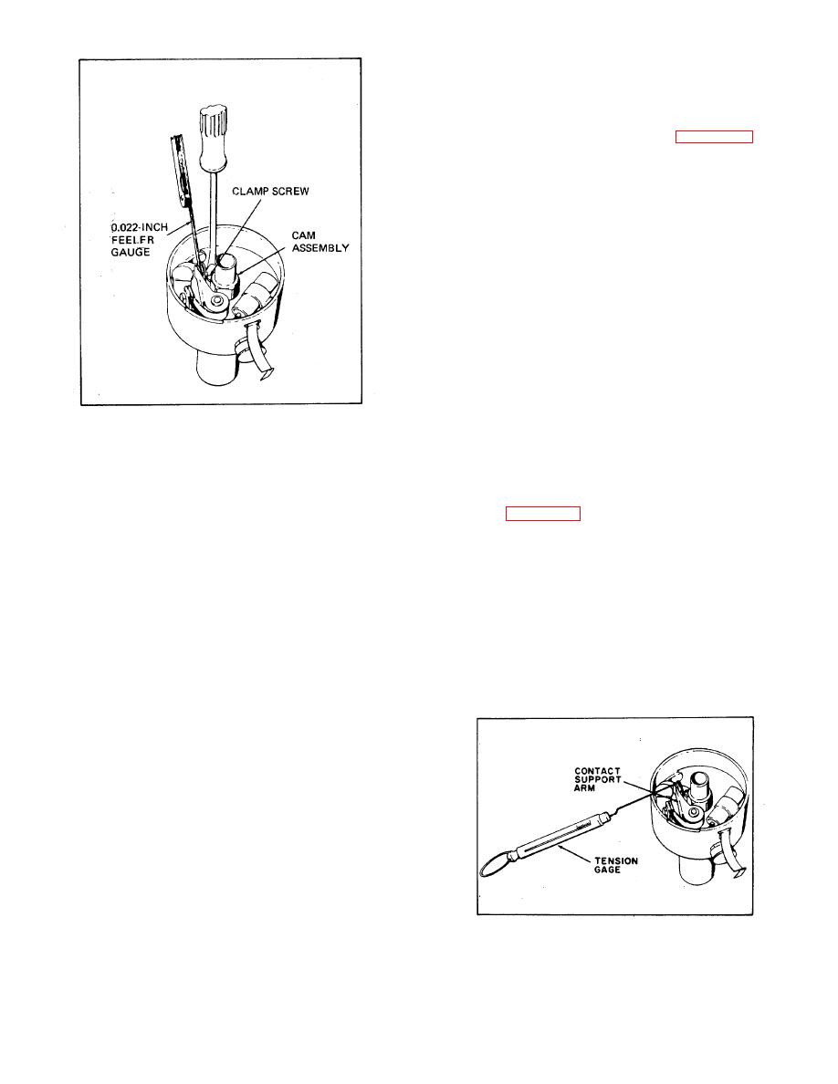
Figure 5-4. Contact Gap Adjustment |
|
||
| ||||||||||
|
|
 to see if distributor lines up with distributor cap segment
connected to No. 1 cylinder and that the remaining ones
are connected in the firing order of 1-5-3-6-24.
5-60. DISTRIBUTOR ADJUSTMENTS.
a. Contact gap adjustment (See Figure 5-4). The
contact point opening must be set to specification.
Points set too close tend to burn and pit rapidly. Points
with excessive separation tend to cause a weak spark at
high speed. Rotate breaker cam until breaker lever
rubbing block is on the high point of the cam lobe, thus
giving the maximum point opening. Loosen the clamp
screw, holding the contact support and adjust point
opening by turning screw on contact support. Contact
opening should be 0.022 inch. Tighten clamp screw and
check with feeler gauge again. The cam angle of the
distributor is 31 deg to 37 deg.
NOTE
The contact points should be cleaned
before adjusting if they have been in
service.
b. Contact point pressure check. Contact point
Figure 5-4. Contact Gap Adjustment
pressure must fall within the limits given. Weak tension
will cause point chatter and ignition miss at high speed,
spotting the engine. When the dead center mark on the
while excessive tension will cause undue wear of contact
flywheel lines up with the mark across the center of the
points and cam. Check the contact point pressure with a
hole in the bellhousing, the pistons for No. 1 and No. 6
tension gauge calibrated to indicate ounces of pull, as
cylinder are in top dead center position.
shown in Figure 5-5. The amount of pull required to
a. The first step in setting or checking the ignition
open the gap must be between 17 to 21 ounces.
timing is to locate the dead center mark and line it up
Replace the contact support arm if it is not within these
with the mark on the bellhousing. To determine whether
limits.
the engine is in firing position for No. 1 or No. 6, the
engine can be cranked with spark plugs removed to
5-61. SPARK PLUG SERVICING.
determine the compression stroke of one of these
a. Clean spark plugs with standard spark plug
cylinders or the valve cover assembly can be removed
cleaning equipment. If the electrodes are excessively
and the position of valves noted. If both tappets for No.
burned, install new spark plugs. Tighten to 30 foot-
1 cylinder are clear, indicating that the valves are closed
pounds torque.
and exhaust on No. 6 is not completely closed, this will
b. Using a round feeler gauge, check for proper
indicate firing position for No. 1 cylinder.
gap between the spark plug electrodes. Adjust the gap
b. To check accurately the exact point of contact
to 0.030 inch by bending the side electrode only.
opening, use a test light. Connect the test light in series
with primary circuit (when ignition switch is on). The test
light will be lighted when ignition contacts are closed and
not lighted when contacts are open.
c. To change ignition timing, loosen screw holding
advance arm to distributor and turn distributor until
correct timing is obtained and then tighten screw.
Clockwise rotation will advance spark and counter-
clockwise rotation will retard it. If distributor is being
retimed after having been removed, it is necessary
Figure 5-5. Contact Point Pressure Check
34
|
|
Privacy Statement - Press Release - Copyright Information. - Contact Us |
