 |
|||
|
|
|||
|
|
|||
| ||||||||||
|
|
 Operate engine until temperature gauge stops rising and
CAUTION
remains stationary. Without changing engine speed, put
Do not hold air or water hose too
end of rubber tube in bottle of water. Be sure there are
close to radiator or use too great a
no kinks or sharp bends to restrict air flow. Watch for air
pressure as damage to the radiator
bubbles in the water as an indication that air is entering
may result. Clean out any stoppage
the cooling system. Correct the condition by tightening
in drain cocks with a soft wire.
cylinder head screw assemblies, water pump mounting
bolts, hose clamps and all fittings. Replace all hose that
5-54. FILL 'SYSTEM. Close radiator and cylinder block
is cracked, swollen or otherwise deteriorated.
drain cocks. Fill system to suit climate conditions as
b. Gas leakage test. Start test with a cold engine.
follows: If the prevailing temperature is above 32. deg
Remove thermostat and reinstall thermostat housing
Fahrenheit, partially fill the system with clean, fresh water
without thermostat or water outlet hose. Add water to
(soft, if possible). Add corrosion inhibitor compound and
level of housing outlet. Disconnect drive belt from fan
fill system with water until coolant is evident at radiator
and water pump pulley. Start engine, accelerate several
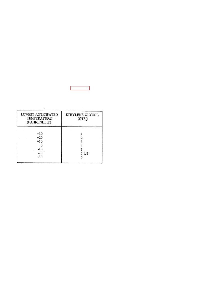
opening. If there is a possibility that temperatures below
times and watch for bubbles in thermostat housing. The
32 deg Fahrenheit will be encountered, pour about
appearance of bubbles or the sudden rise of liquid when
one gallon of water into the radiator and add anti-freeze
accelerating is evidence of exhaust gas leakage into
as required to safeguard cooling system freezing at
cooling system.
Make test quickly before coolant
lowest expected temperature (See Figure 5-3). Fill with
reaches boiling point as steam will give misleading
water to level of filler neck, install radiator cap, start
results. Correct the condition by replacing cylinder head
engine and operate at fast idle until temperature gauge
gasket and repeat test. If leakage is still evident, a
shows normal operating temperature. Stop engine and
cracked cylinder head, requiring a major engine
check coolant level. Add water, if necessary.
overhaul, is indicated. Install thermostat and connect
radiator hose. Fill radiator. Install and adjust fan and
alternator drive belt.
5-56. RUST PREVENTIVES. The cooling system must
be free of rust and scale to maintain efficiency of the
system.
The use of corrosion inhibitor compound
reduces or prevents corrosion of metals and prevents
formation of scale. Inhibitors are not cleaners and do not
remove rust or scale already formed. Treating the
cooling system with the inhibitor consists of adding the
compound to the coolant. The inhibitor should be
renewed periodically, especially if the system has been
cleaned or flushed.
5-57. FAN BELT ADJUSTMENT. Loosen the two cap
screws attaching generator to the mounting bracket.
Figure 5-3. Anti-freeze Requirements
Loosen the cap screw attaching generator to the
adjusting arm and move generator either away from or
5-55. LEAKAGE TESTS. Air in the cooling system or
toward the engine as necessary to obtain correct belt
exhaust gas leaking into the system, causes rapid
tension. A light pressure applied to the belt mid-way
corrosion and rust formations which will eventually clog
between the generator and water pump must produce a
the system and cause overheating and loss of coolant.
one-inch belt deflection. When properly adjusted tighten
Air may be drawn into the system due to low liquid level
the cap screw attaching generator to the adjusting arm
in the radiator, leaky water pump or loose fittings.
and then tighten the two cap screws between generator
Exhaust may be blown into the cooling system, past the
and mounting bracket.
cylinder head gasket or through cracks in the cylinder
head and crankcase.
5-58. IGNITION SYSTEM.
a. Air suction test.
Bring level of coolant to
maximum capacity in radiator. Drain out one and one-
5-59. IGNITION TIMING. Ignition timing requires
half pints of coolant to prevent overflow during test. Be
adjustment of the distributor assembly so that high
sure radiator cap is in good condition and will make an
voltage impulses are delivered to the spark plugs in
air-tight seal. Attach a length of rubber tubing to the end
proper time relation to piston position. Efficient operation
of the overflow tube, being certain the connection is air-
of the engine requires that a spark be produced in the
tight.
combustion chamber when the piston is in top dead
center on the compression stroke. Timing is checked by
means of a timing hole through the bellhousing for
33
|
|
Privacy Statement - Press Release - Copyright Information. - Contact Us |
