 |
|||
|
|
|||
|
|
|||
| ||||||||||
|
|
 and equally applied to both front wheels. Note any
"mushiness" or "creeping" of. the brake pedal or A
tendency of the wheels to lock, pull to one side or
produce unusual noises. Test the hand brake with the
vehicle on an incline, noting if there is any tendency to
5-36. STEERING. Check the steering wheel travel for
hard steering, poor return to center and noises. The rear
wheels should have a tendency to straighten out when
pressure on the steering wheel is relaxed.
5-37. UPRIGHT ASSEMBLY HYDRAULIC SYSTEM.
Check the hydraulic system with a substantial load on
the forks by testing operation of both the tilt and hoist
Figure 5-1. Cylinder Head Screw Tightening
cylinders through their complete area of movement.
Pushing the control valve handle marked "HOIST" back
c. A final tightening and checking of torque should
raises the forks to the extreme top of the upright
be made after the engine has been run and is still warm.
assembly. With load raised and control in neutral
position, check for any creep-down of the loaded fork.
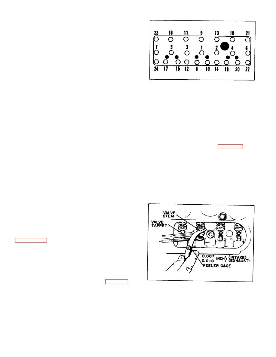
5-43. INTAKE AND
EXHAUST
VALVE
TAPPET
After test, inspect hydraulic system for leaks. Slowly
ADJUSTMENT.
push lever forward and allow the forks to bottom by
gravity. If, in raising hoist, the lever is not returned to
a. Start engine and allow it to run until normal
neutral when top is reached, the over-load bypass in the
operating temperature is reached. Stop engine, remove
control valve will open automatically and detour the flow
valve cover assembly and cover gasket.
of oil back to the reservoir tank. This action is indicated
b. Start engine and insert feeler gauge between
by a buzzing sound which is normal. Note if there is any
valve tappet and valve stem. (See Figure 5-2) Loosen
tendency of channels to bind and be sure there is
the tappet, adjusting lock nut, and adjust tappet until
complete freedom of the crosshead assembly, both up
there is a clearance of 0.007 inch on the intake and
and down. In testing of the tilt operation, when lever
0.010 inch on the exhaust. Tighten the tappet adjusting
marked "TILT" is pulled back to its extreme, the forks
lock nut when properly adjusted.
should tilt up and back. When the tilt lever is pushed
c. Repeat the above adjustment procedures on all
forward, the forks should tilt out or down. Both tilting
intake and exhaust valve tappets. Stop the engine and
actions are accomplished by hydraulic pressure. Note
inspect all visible valve components for wear or
any tendency for either the hoist or tilt action to hesitate
weakness.
or mush.
d. Install valve cover assembly and a new cover
5-38. LIGHTS. Turn on ignition switch and check
gasket.
operation of stoplight by pressing brake pedal. Turn on
taillight.
5-39. ORGANIZATIONAL MAINTENANCE.
5-40. The following maintenance services are to be
performed by the using organization personnel and are
referenced to the periodic service inspection starting with
with the tools and equipment normally available at the
using organization.
5-41. ENGINE ASSEMBLY.
5-42. CYLINDER HEAD TIGHTENING.
a. Using a torque wrench, tighten cylinder head
nuts and stud nuts in the sequence shown in Figure 5-1.
b. Tighten cylinder head nuts to a torque of 35 to
Figure 5-2. Valve Tappet Adjustment
40 foot-pounds.
31
|
|
Privacy Statement - Press Release - Copyright Information. - Contact Us |
