 |
|||
|
|
|||
|
Page Title:
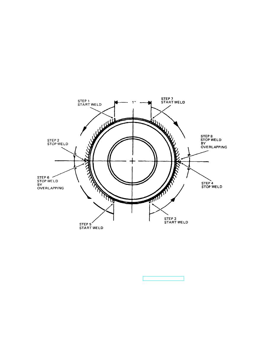
Figure 10-5. Bearing stud welding procedure |
|
||
| ||||||||||
|
|
 TM 10-3930-621-34
3/
(5) Comply with the following welding specifications
Plate Thickness Range ............ 8" - 1"
using bearing stud welding procedure (fig. 10-5):
Electrode:
Type ...................................... Stick
Process ............................ Shielded Metal Arc
Class ..................................... E 7018 (hydrogen free)
3/
Size ....................................... 8"
Equipment ........................ Manual
Flux ....................................... Electrode Covering
Settings:
Weld Type and Size ................. 1/4" Fillet
Current.............................. A.C.
Number of Passes ................... 1
Amps ........................... 275 / 325
Position .................................... Horizontal
Volts............................. 31/33
Preheat..................................... 400F
Base Metal........................ (1) AC 1035-D
Interpass .................................. 250F
.................................................. (2) AC 41L40-HT (roller
stud)
Postheat ................................... None
Figure 10-5. Bearing stud welding procedure
(6)
When welding is completed
g. Replace defective parts as authorized.
remove all slag, weld spatter, and excessive weld
h. If studs (3, fig. 10-3) or outer mast bearings (6)
material.
are replaced, attaching screws (38) must also be
(7)
Finished
weld
must
be
replaced.
magnafluxed for defects.
10-14. Assembly
(8)
Remove defective material with
a pencil grinder in 0.010-0.020 of an inch passes and
Note. Prior to assembly, lubricate all parts per
visually
inspect
for defects
after each
pass.
TM 103930-621-12.
Magnaflux is to confirm disappearance of defect.
a. Refer to figure 10-3 and assemble as follows: b.
d. Inspect mast channels for misalinement, broken
Install lubrication fittings (66 and 67) and bearings (2) in
welds, excessive wear, worn or damaged wear strips.
outer mast (1).
e. Inspect pivot and tilt cylinder brackets on outer
c. Assemble intermediate mast (7) as follows:
mast for wear or damage. Check pivot bearing.
(1) Install bearings (6) and same size and
quantity of shims (4 and 5) on welded intermediate mast
f. Repair by welding if practical, provided heat
bearing studs (8), if bearings and shims were removed
distortion is avoided.
during disassembly.
10-10
|
|
Privacy Statement - Press Release - Copyright Information. - Contact Us |
