 |
|||
|
|
|||
|
Page Title:
Section III. WHEEL AND TIRE ASSEMBLIES |
|
||
| ||||||||||
|
|
 TM 10-3930-621-34
Section III. WHEEL AND TIRE ASSEMBLIES
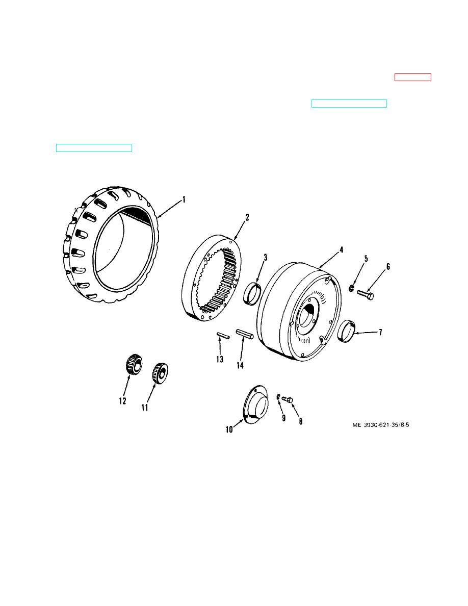
(1) If inspection indicates replacement is
8-11. Description
necessary , remove tire (1) from wheel (4) (para 8- 17).
Drive wheel assemblies consists of a wheel, which
(2) Remove hub cap (10), cotter pin and wheel
serves as a brake drum, a bull gear, a tire, and inner and
nut, inner bearing cone (12), outer bearing cone (11),
outer tapered roller bearings. Steering wheel assemblies
and grease shield (TM 10-3930-621- 12).
contain a wheel, a tire, and inner and outer tapered roller
(3) Remove screws (6), lock washers (5), and
bearings. Each wheel assembly is secured to its
bull gear (2) from wheel (4).
respective axle by a nut and cotter pin located under a
(4) Turn wheel (4) over, and drive bull gear (2)
hub cap.
from wheel using same screws (6). Tighten screws
8-12. Removal
evenly.
Refer to TM 10-3930-621-12 for removal procedures or
(5) Remove pins (13 and 14) from bull gear (2).
either steering or drive wheel assemblies.
(6) Using bearing cup puller, remove bearing
8-13. Disassembly
cups (3 and 7) from wheel (4).
1.
Tire
8. Screw
2.
Bull gear
9. Lock washer
3.
Inner bearing cup
10. Hub cap
4.
Drive wheel
11. Outer bearing cone
5.
Lockwasher
12. Inner bearing cone
6.
Screw
13. Pin
7.
Outer bearing cup
14. Spring pill
Figure 8-5. Drive wheel assembly, exploded view.
8-7
|
|
Privacy Statement - Press Release - Copyright Information. - Contact Us |
