 |
|||
|
|
|||
|
Page Title:
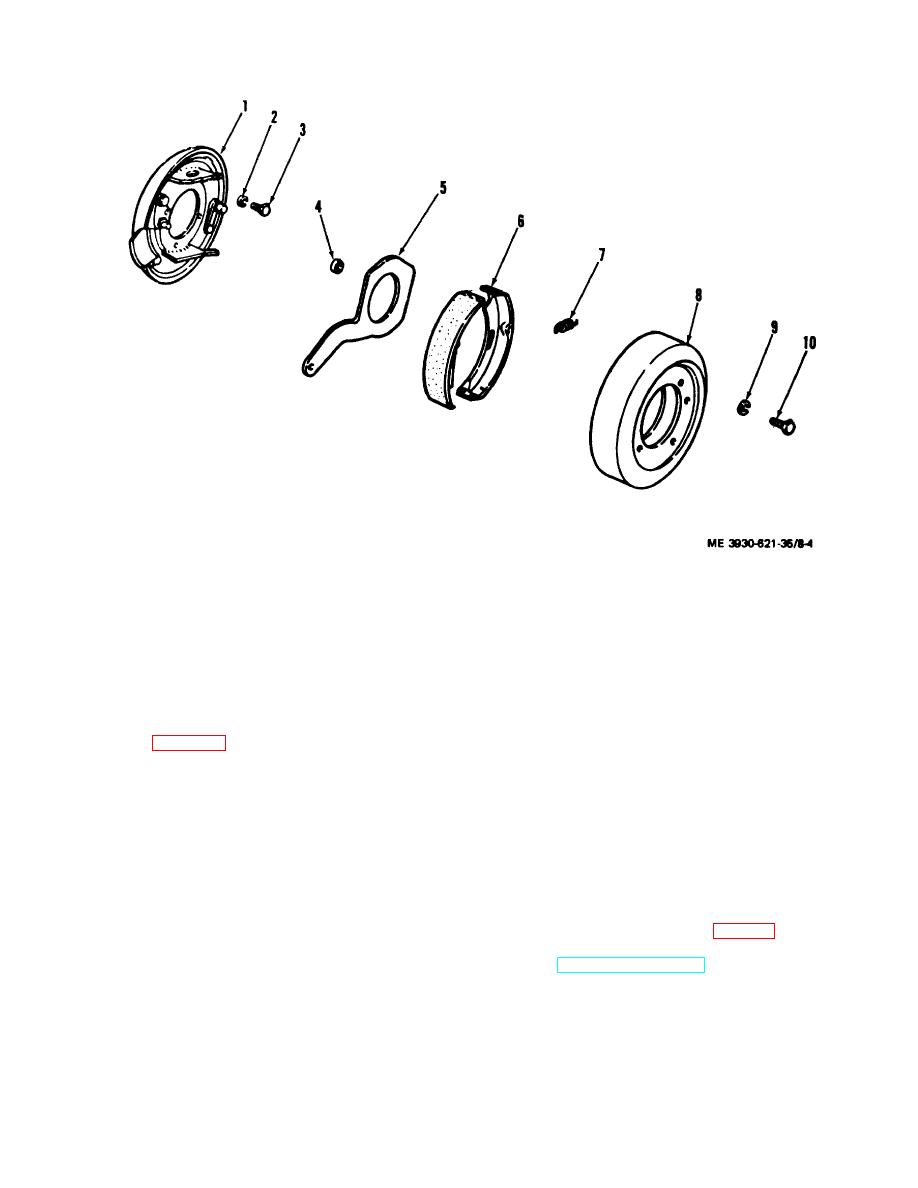
Figure 8-4. Parking brake assembly exploded view. |
|
||
| ||||||||||
|
|
 TM 10-3930-621-34
1.
Backing plate
6. Brake shoes
2.
Lock washer
7. Spring
3.
Screw
8. Drum
4.
Roller
9. Lock washer
5.
Lever
10. Screw
Figure 8-4. Parking brake assembly exploded view.
8-9. Inspection
b. Lightly coat backing plate (1) wear pads and
a. Refer to figure 8-4 and inspect as follows:
pawls, cam lever (5), and brake shoe (6), wear points
b. Check backing plate (1) for distortion, loose or
with brake lubricant. Avoid excessive lubricant as
sheared rivets, and worn pawls.
grease soaked linings are dangerous.
c. Check brake lining (6) for wear or grease
c. Attach backing plate (1) to differential carrier
saturated- Wear limit for parking brake lining is 0.0625 of
housing with screws (3) and lock washers (2).
an inch.
d. Slide brake shoes (6) on backing plate (1) and
d. Check brake shoes (6) for worn pawl holes, lever
install return springs (7).
contact areas, or wear pads.
e. Install cam lever (5) and rollers (4) on backing
e. Check brake drum (8) for cracks, scoring or other
plate (1).
damage.
f. Position brake drum (8) and install differential
f. Replace damaged parts as authorized.
pinion shaft flange on drive shaft (para 6- 5).
g. Always replace shoe return springs (7) during
g. Connect parking brake cable and install floor and
reassembly.
toe plates (TM 10-3930-621-12).
8-10. Assembly
h. Adjust parking brake cable (TM 10-3930- 621-
a. Refer to figure and assemble as follows:
12).
8-6
|
|
Privacy Statement - Press Release - Copyright Information. - Contact Us |
