 |
|||
|
|
|||
|
|
|||
| ||||||||||
|
|
 TM 10-3930-621-34
7-3. Spindle
(6) Remove self-locking nut and grease shield
a. Removal
(27) from spindle. Using puller, pull spindle from axle.
(1) Remove drive wheel assembly (TM 10-
b. Cleaning, Inspection, and Repair.
3930-621-12).
(1) Clean all parts with cleaning compound,
(2) Refer to) figure .7-3 and remove spindle from
solvent (Spec.
P-S-661).
Dry thoroughly with
housing as follows:
compressed air.
(3) Remove screws 114, fig. 7-3) and lock
(2) Inspect spindle and attaching parts for
washers t15) attaching dust shield (13) and remove
damage.
shield.
(3) Replace damaged parts as authorized.
(4) Loosen self-locking nut (26) approximately
(4) Refer to paragraph 1-4 for Repair and
three turns.
Replacement Standards.
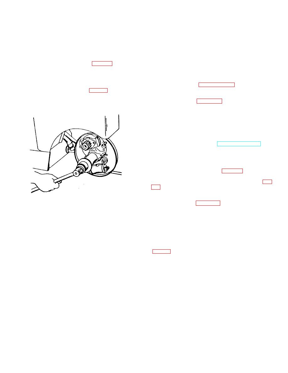
(5) Install suitable puller fig. 7-4) and remove
c. Installation.
spindle (28) from axle part away until spindle is loose in
(1) Refer to figure 7-3 and install spindle as
housing.
follows:
(2) Aline spindle (28) in housing (8) and secure it
to inside of housing with washer (27) and self-locking nut
(26). Tighten nut until spindle is completely seated in
axle.
(3) Install dust shield (13) and secure with lock
washers (15) and screws (14).
(4) Install drive wheel (TM 10-3930-621-12).
7-4. Differential Assembly
a. Disassembly.
(1) Remove drive wheel assemblies (TM 10-
3930-621-12).
(2) Remove axle shafts (para 7-2 a) and drain
lubricant from axle housing.
(3) Remove cover mounting bolts (4 and 5, fig.
(4) Remove housing cover (6) and gasket (2).
Discard gasket.
Figure 7-4. Removing spindle
(5) Refer to figure 7-6 and disassemble carrier
assembly as follows:
(a) Mark caps and axle housing to
provide identification for proper installation.
(b) Remove bolts (251, screws (22), lock
washers (24) and lock (23) from carrier. Remove
bearing caps from carrier.
(c) Remove differential assembly (27)
with attached adjusting nuts, bearings, and bearing cups
7-4
|
|
Privacy Statement - Press Release - Copyright Information. - Contact Us |
