 |
|||
|
|
|||
|
|
|||
| ||||||||||
|
|
 TM 10-3930-621-34
fourth rings should measure 0.015-0.055 of a inch. If the
temperature before the following clearance checks are
gap is smaller than the minimum specified, file ends of
made.
ring until the desired gap obtained.
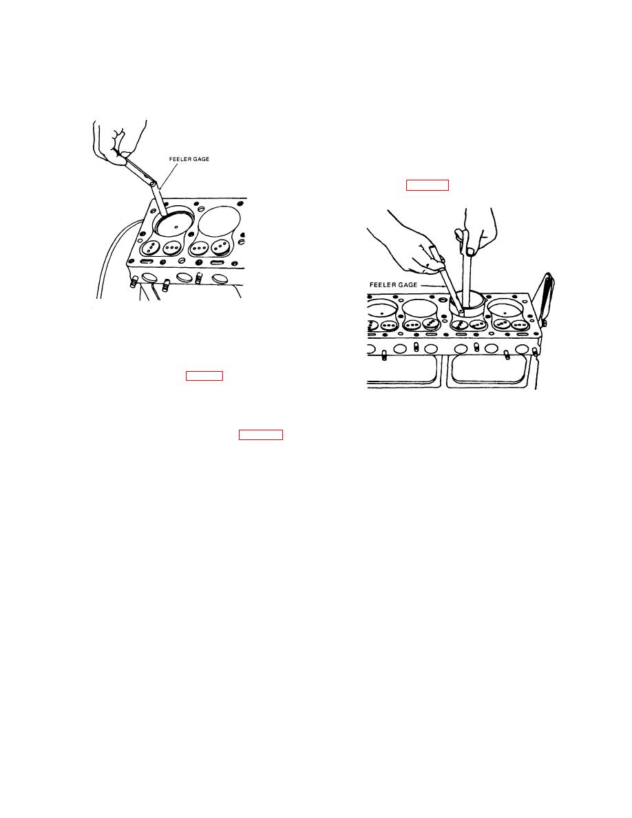
(2) Select a piece of 0.5 inch wide feeler gage
stock 8 to 10 inches long and 0.0003 inch thick. This
feeler stock must be perfectly flat and free of nicks or
scratches. Attach a feeler gage to an accurate spring
scale having a 10 pound full scale reading.
(3) Hold feeler gage along the side of cylinder
bore then insert piston and rod assembly in to bore in
o
normal running position. Gage must be positioned 90
from piston pin (fig. 3-10).
ME3930-621-35/3-9
Figure 3-9. Checking ring gap.
d. Checking Ring Side Clearance
(1) Install fitted rings (1, fig. 3-8) on the pistons
to be used in the specific bore in which the ring gap test
was performed.
ME3930-621-35/3-10
(2) Check rings for the proper side clearance
between rings and sides of the piston grooves. The
Figure 3-10. Checking piston clearance.
clearance tolerance should be as specified in table 1-1. If
the side clearance is less than minimum clearance
(4) A maximum pull of eight pounds should withdraw the
exceeds the specified tolerance, lay a piece of fine
feeler gage from between piston and bore.
emery cloth on a flat surface and rub the ring lightly until
(5) Repeat steps (3) and (4) above at three more
desired clearance is obtained. If side clearance exceeds
points 90 apart around the cylinder bore.
the specified tolerance, replace the ring.
(6) Repeat steps (3), (4), and i5) above at both
e. Checking Pin Clearance In Piston.
ends of the cylinder bore to insure equal diameters at top
(1) Measure piston pin clearance in piston.
and bottom of bore.
Design tolerance is from 0.0002 to 0.0004 inch loose. If
3-30. Assembly and Installation
too tight ream out pin holes.
a. Oil cylinder wall and piston with internal combustion
(2) measure piston pin clearance in the
engine lubricating oil (OE).
connecting rod bushing. The desired clearance is from
b. Be certain that ring gaps are equally spaced around
0.0002 to 0.0006 inch loose, replace bushing.
the circumference of the pistons.
f. checking piston Skirt to Cylinder Clearance
c. Compress rings with ring compressor, tapping the
(1) Pistons must be allowed reach room
compressor lightly around the rings to allow the rings to
close evenly.3-13
3-13
|
|
Privacy Statement - Press Release - Copyright Information. - Contact Us |
