 |
|||
|
|
|||
|
|
|||
| ||||||||||
|
|
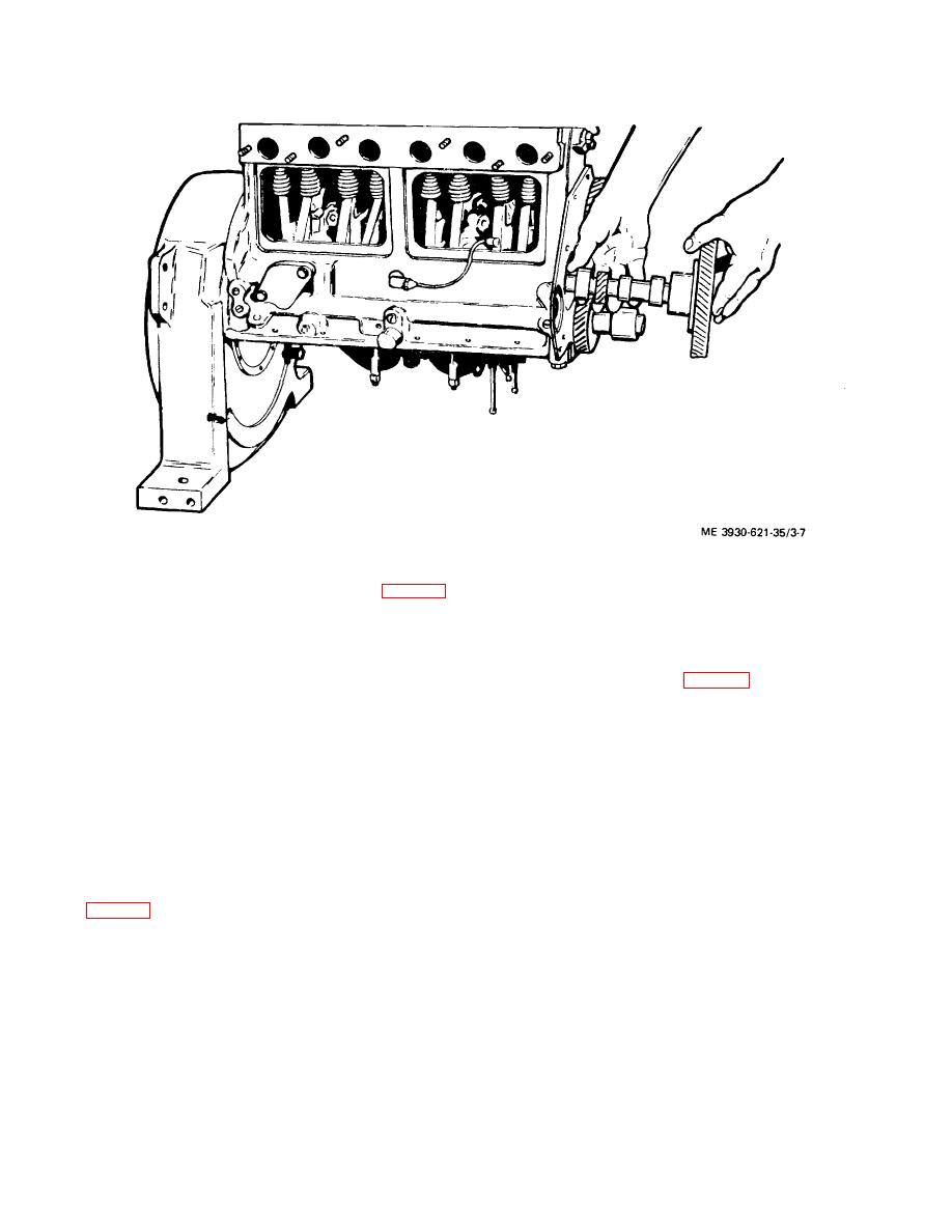 TM 10-3930-621-34
Figure 3-7. Removing Camshaft
f. Remove sleeve bearings (9,10, and 22, fig. 3- 6)
c. If a condition of insufficient end play is found (less
thin enough to collapse and remove. Press sleeve
than 0.002 inch), use one or two thin shims between the
bearings out, using new sleeve bearings, if possible.
journal shoulder and the face of the drive gear.
g. If removal of the drive gear (16) is necessary,
3-24. Installation
proceed as follows:
a. If drive gear (16, fig. 3-6) was removed and
(1) Remove retaining ring (17).
disassembled, reassemble as follows:
(2) Press the gear from the camshaft (21) using
(1) Clean out gear and camshaft (21) oil
a suitable arbor press and support plate. Lock plate (18)
passages.
and thrust plate (19) may now be removed from the
(2) Install lock plate (18) and thrust plate (19) on
camshaft.
camshaft.
h. The camshaft should be inspected for wear,
(3) Press fit drive gear on shaft, 0.002 press
scoring, and alignment.
maximum, using suitable arbor press and support plate.
i. The bearings should be inspected for wear, scoring,
(4) Install retaining ring (17) on camshaft.
or burnt condition.
Damaged bearings should be
b. Install the sleeve bearings (9, 10 and 22) in engine
replaced.
block by pressing bearings in place.
3-23. End Play Adjustment
c. Slowly insert camshaft assembly in sleeve bearings,
a. Check camshaft end play by mounting thrust plate
using caution not to damage any parts. Align "C" marks
(19, fig. 3-6) and lock plate (18') on shaft (21) and
on crankshaft and camshaft gears and mesh gears.
measuring distance between shaft journal and thrust
d. Insert thrust plate screws (15) through drive gear
plate with feeler gauge.
(16) holes and tighten securely.
b. If measurement exceeds 0.006 inch, replace thrust
e. Slowly lower valves (1), springs (4), and tappets (8)
plate with one of suitable thickness to provide 0.002 to
that were raised for removal procedure.
0.006 inch clearance between journal and thrust plate.
3-11
|
|
Privacy Statement - Press Release - Copyright Information. - Contact Us |
