 |
|||
|
|
|||
|
Page Title:
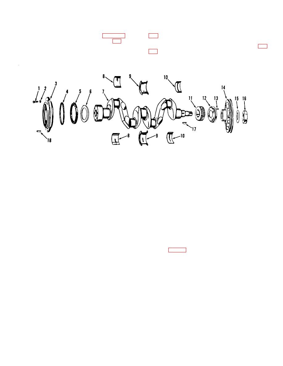
Figure 3-3. Crankshaft exploded view. |
|
||
| ||||||||||
|
|
 TM 10-3930-621-34
j. Remove connecting rod bearing caps (para 3-26).
k. Remove main bearing cap lock plates (29, fig.
24 and 30).
l Remove thin walled outer bearings (8, 9 and10, fig.
ME 3930-621-3513-3
1.
Bolt
10.
Front main bearing
2.
Lock washer
11.
Crankshaft timing gear
3.
Bearing plate
12.
Front deflector
4.
Bearing plate gasket
13.
Drive screw
5.
Oil seal
14.
Crankshaft pulley
6.
Rear deflector
15.
Recessed washer
7.
Crankshaft
16.
Self-locking nut
8.
Rear main bearing
17.
Key
9.
Center main bearing
18.
Pin
Figure 3-3. Crankshaft exploded view.
m. Carefully lift crankshaft from bearing seats.
Avoid nicking or bumping the bearings or journal
surfaces (fig. 3-4).
3-5
|
|
Privacy Statement - Press Release - Copyright Information. - Contact Us |
