 |
|||
|
|
|||
|
Page Title:
Service Brake Brake Shoes |
|
||
| ||||||||||
|
|
 (2) Install master cylinder on frame and secure
with two screws and lock washers. Connect ground
wire with rear mounting screw.
(3) Connect clevis to brake pedal and secure with
clevis pin and cotter pin.
(4) Connect hydraulic brake line to master cylin-
der.
(5) Install stop light switch in fitting in master
cylinder and connect wires to switch.
(6) Refer to c below to fill master cylinder and
bleed brake hydraulic system.
c. Bleeding Brake Hydraulic System. Each time
the system has been drained or refilled or a part has
been disconnected or replaced, the system must be
bled as follows:
(1) Remove filler cap on master cylinder and fill
to proper level (3/8 to 1/2 inch from top).
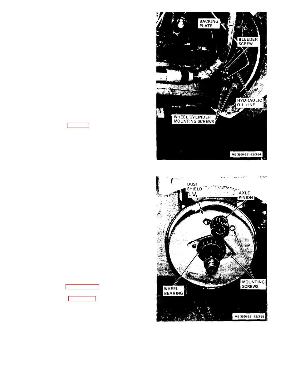
(2) Connect a bleeder hose to bleeder screw
on front wheel (fig. 3-54). Submerge other end of
hose in a glass jar filled with brake fluid.
(3) Open the bleeder screw one turn.
(4) Slowly depress brake pedal to end of travel
and release pedal. Observe hose in jar and repeat
pumping of brake pedal until no air bubbles escape
Figure 3-54. Service brake pedal
from the hose. Hold pedal at bottom of travel and
adjustment
close bleeder screw to keep additional air from
entering system.
Note. While pumping pedal, check fluid level in master cylin-
der. Add fluid to keep cylinder as close to full as possible at all
times during bleeding process.
(5) Repeat bleeding operation on remaining front
wheel bleeder screw.
(6) Fill master cylinder to proper level after
bleeding operation.
Caution: Discard fluid salvaged from brake sys-
tem during bleeding operation. Do not use in sys-
tem.
3-64. Service Brake Brake Shoes
a. General. The service brake brake shoes are
mounted beneath the dust shield. The shoes are
attached to the wheel cylinders and return springs.
b. Removal.
(1) Refer to paragraph 3-67 and remove the wheel
and tire assembly.
(2) Refer to figure 3-55 and remove the brake
dust shield as follows:
(a) Remove four screws and lock washers
securing dust shield to axle. Remove wheel bearing
from axle.
(b) Carefully remove dust shield from around
Figure 3-55. Service brake dust shield,
installed view.
axle pinion.
3-47
|
|
Privacy Statement - Press Release - Copyright Information. - Contact Us |
