 |
|||
|
|
|||
|
|
|||
| ||||||||||
|
|
 (4) If above steps do not provide proper braking
(6) Remove nut and clevis from master cylinder.
action, adjust cable.
(5) Refer to figure 3-51 and remove cotter pin,
washer, and clevis pin securing clevis to cam lever.
(6) Loosen clevis locknut and turn clevis three
or four turns clockwise on cable. Install clevis on
cam lever and engage brake.
(7) Check braking action and adjust cable (6
above) until action is correct.
(8) Tighten locknut to secure adjustment.
3-62. Service Brake Pedal and Linkage
inching pedal are mounted on a common shaft. De-
pressing the brake pedal actuates the master
cylinder. Depressing the inching pedal operates the
inching valve in the transmission control. Further
depression of inching pedal will depress the brake
pedal and operate the service brakes.
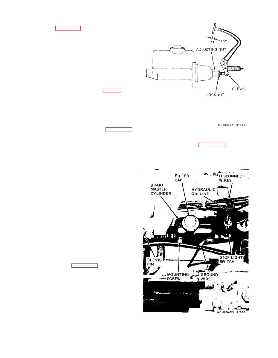
Figure 3-52. Service brake pedal
and adjust the brake pedal travel as follows:
adjustment
(1) Pedal free play should be adjusted to one-
half inch travel to allow master cylinder piston to re-
the master cylinder.
turn to off position and reduce unusable length of
(1) Install clevis and nut on master cylinder push
stroke in the master cylinder.
rod.
(2) Remove the floor plate.
(3) Slowly depress the brake pedal and check
free travel. Observe push rod action at master cylin-
der.
(4) If free travel is more or less than one-half
inch, loosen locknut on clevis at master cylinder and
turn adjusting nut to adjust travel in direction re-
quired.
(5) After adjustment, check travel. When travel
is within limits, tighten locknut.
(6) Depress inching pedal. At lower end of travel,
inching pedal should contact brake pedal and apply
brakes.
(7) If inching pedal adjustment is required refer
to direct and general support personnel.
3-63. Service Brake Master Cylinder
brake master cylinder as follows:
(1) Remove the floor plate.
(2) Disconnect wires and remove stop light
switch from master cylinder.
(3) Disconnect hydraulic oil line from master
cylinder.
(4) Remove cotter pin and clevis pin and dis-
connect clevis from brake pedal push rod.
(5) Remove two screws and lock washers securing
Figure 3-53. Service brake master
master cylinder to frame and remove master cylinder.
cylinder, installed view.
3-46
|
|
Privacy Statement - Press Release - Copyright Information. - Contact Us |
