 |
|||
|
|
|||
|
|
|||
| ||||||||||
|
|
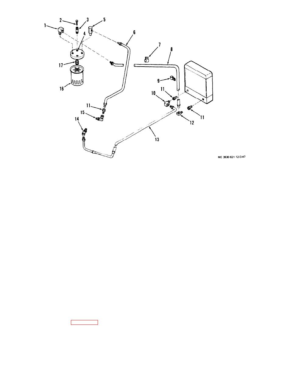 1.
Elbow
10. Elbow
2.
Screw
11. Adapter
3.
Spacer
12. Elbow
4.
Filter base
13. Line assembly.
5.
Elbow
cooler to
6.
Hose assembly,
transmission
filter to
14. Adapter
transmission
15. Elbow
7. Clamp
16. Filter
8. Hose assembly,
17. Nipple
filter to cooler
9. Clamp
Figure 3-47 Transmission oil cooler lines,
exploded view.
Section XIV. PROPELLER SHAFT
3-55. General
propeller shaft as follows:
sion to the front drive axle. The propeller shaft is
(1) Remove lock wires and eight screws attaching
attached to flanges at the transmission output shaft
propeller shaft universal joints to transmission and
and parking brake.
parking brake flanges.
(2) Slide output shaft into transmission to allow
transmission to the front drive axle.
room for removal of propeller shaft. Remove pro-
peller shaft.
3-56. Propeller Shaft
3-42
|
|
Privacy Statement - Press Release - Copyright Information. - Contact Us |
