 |
|||
|
|
|||
|
|
|||
| ||||||||||
|
|
 the combination rear lamp as follows:
(a) Install light on bracket and secure with
two nuts and washers. Connect wires to connectors.
(b) Install lamp. depressing lamp into socket
and turning lamp one-quarter turn clockwise.
(c) Install lens in light and secure by instal-
ling lock ring in groove in lamp.
3-50. Horn and Horn Relay
a. General. The horn and horn relay are mounted
on the right post and are protected by the right hand
cowl.
b. Tests and Adjustments. In the event the horn is
not operating properly, check the battery voltage
before proceeding with the following tests.
(1) Remove three screws, one nut, and lock wash-
ers and remove right hand cowl.
(2) In event the horn is producing a weak signal
proceed as follows:
terminal and ground. Press the horn button and ob-
serve the voltage on voltmeter.
(b) If voltage is between zero and 10.7 volts,
check for an open circuit, defective horn relay, de-
fective wiring, or shorted horn coil.
(3) If voltage is normal and horn signal is weak,
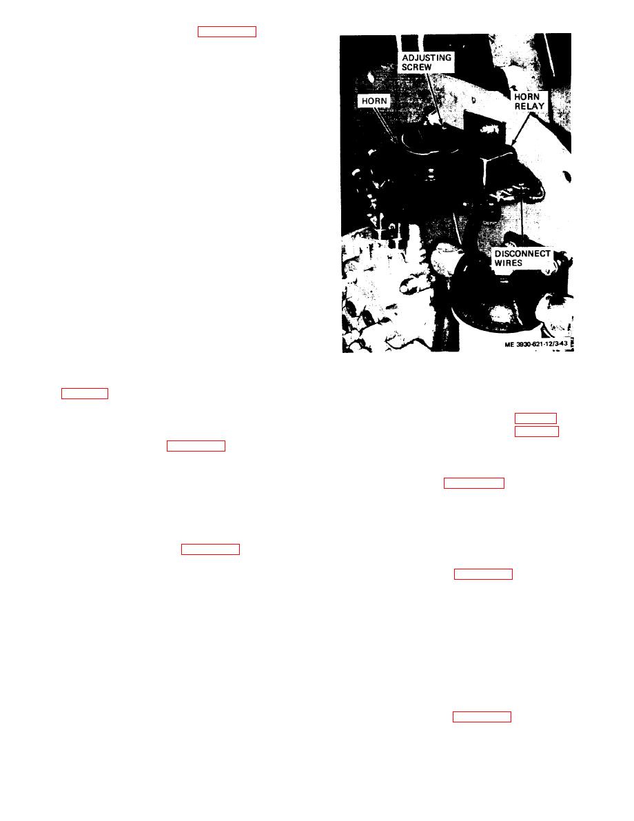
Figure 3-43. Horn and horn relay, installed view.
increase volume by using volume adjusting screw
ing the engine unless the transmission is in neutral.
increase volume; counterclockwise to decrease.
Placing the transmission shift lever (fig. 2-2) into
(4) If defective horn relay is indicated, replace
neutral (N) position moves a cam lever (fig. 3-44) into
relay.
contact with the switch roller, closing the snitch and
completing the circuit. Check cam adjustment (d
and horn relay.
below) before replacing the switch.
(1) Tag and disconnect wires from horn and horn
relay.
switch as follow:
(2) Remove two nuts and washers from studs
(1) Disconnect wires leading from switch at con-
attaching horn to mounting bracket and remove horn.
nectors.
(3) Remove screw, nut, and lock washer securing
(2) Remove two screws, nuts, lock washers, and
horn relay to bracket and remove relay.
flat washers securing the switch to the support and
remove the switch.
horn and horn relay as follows:
(1) Install horn relay on bracket and secure with
switch as follows:
screw, nut, and lock washer.
(1) Install switch on steering column support and
(2) Install horn on bracket and secure with two
secure with two screws, nuts, lock washers, and flat
nuts and washers on horn studs.
washers.
(3) Connect wires to horn and horn relay.
(2) Connect wires from switch to connectors in
(4) Install right hand cowl and secure with three
wires from harness.
screws, nuts, and four lock washers.
(3) Operate shift lever and check switch opera-
3-51. Transmission Neutral Switch
tion. Cam on lever must contact switch roller and
open switch when shift lever is in forward or reverse
a. General. A normally opened switch, connected
positions. Adjust (d below) if necessary.
in series with the starter button and starter solenoid
switch, is attached to the underside of the steering
lever as follows:
column support bracket. The switch prevents start-
3-39
|
|
Privacy Statement - Press Release - Copyright Information. - Contact Us |
