 |
|||
|
|
|||
|
Page Title:
Figure 3-25. Connections for alternator output test. |
|
||
| ||||||||||
|
|
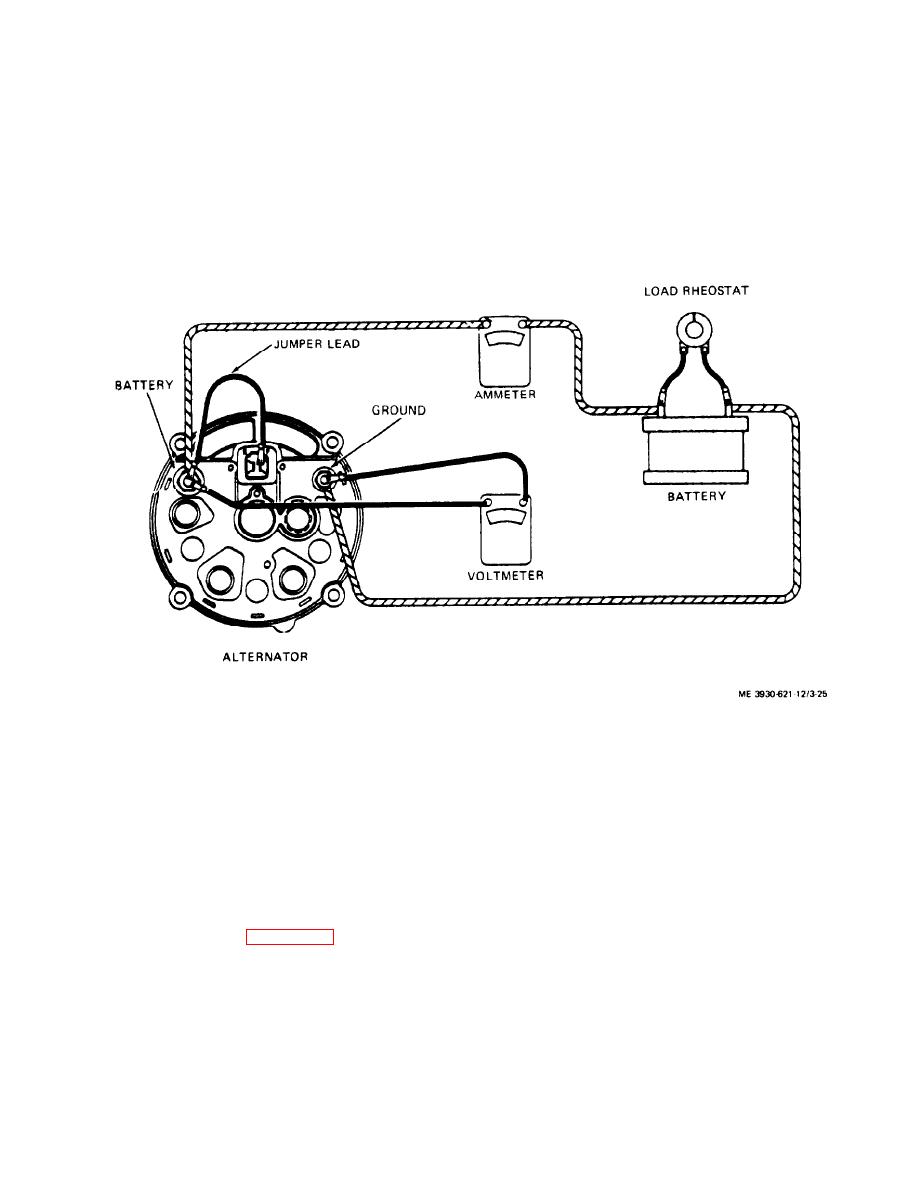 1100 rpm. Voltmeter should read 12 volts and am-
(1) Connect a voltmeter between battery and
meter should read 2.2 to 2.6 amps.
ground terminals as shown.
(5) Increase engine speed to full throttle. The
(2) Disconnect plug from rear of alternator.
voltmeter should read 12 to 14 volts and the am-
(3) Connect a jumper from field terminal to
meter should read 25 to 29 amps.
battery terminal as shown.
(4) Operate engine at a fast idle, approximately
Figure 3-25. Connections for alternator output test.
(4) Loosen screw on adjusting strap and move
alternator far enough toward engine to remove drive
alternator as follows:
belt from alternator pulley. Remove screw, lock
(1) Disconnect the battery ground cable (para
washer and flat washer from alternator and strap.
3-11).
(5) Remove two screws and nuts, and four lock
(2) Disconnect plug connecting R and F circuits.
washers attaching alternator to mounting bracket
(3) Disconnect wires from battery and ground
and remove alternator from engine.
terminals on alternator. Mark wires for correct in-
stallation.
3-27
|
|
Privacy Statement - Press Release - Copyright Information. - Contact Us |
