 |
|||
|
|
|||
|
|
|||
| ||||||||||
|
|
 3-39. Fan and Fan Belt
a. Inspection. Inspect belt for wear. fraying or
deterioration. Check for belt deflection and adjust
(para 3-12), if necessary.
b. Fan Belt Removal and Inspection.
(1) Loosen alternator adjusting strap (fig. 3-5)
to loosen fan belt and slip belt from alternator pulley.
(2) Remove radiator grille and panel (para 3-37).
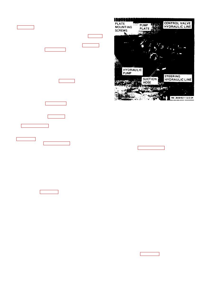
(3) Refer to figure 3-24 and remove hydraulic
pump as follows:
(4) Disconnect three hydraulic lines from hy-
draulic pump.
(5) Remove four screws and lock washers secur-
ing hydraulic pump plate to engine. Remove pump
plate, with pump attached, from engine.
(6) Slip fan belt (18, fig. 3-23) from crankshaft
pulley and work belt up and over fan blades and off
fan pulley.
(7) Install new belt by slipping over fan blades
and around crankshaft pulley and fan pulley.
(8) Refer to figure 3-24 and install hydraulic
Figure 3-24. Hydraulic pump, installed view.
pump and plate and secure with four screws and
(21) securing fan to fan hub on water pump.
lock washers. Connect hydraulic lines to pump. In-
(3) Remove fan (19) and fan pulley (22) from
stall radiator grille (para 3-37).
engine.
(9) Slip fan belt over alternator pulley and refer
(4) Install engine fan as follows:
to paragraph 3-12 and adjust fan belt tension and
(5) Install fan pulley and fan on fan hub, with
secure alternator.
c. Engine Fan Removal and Installation. Refer to
fan pulley engaging fan belt.
(6) Secure fan and pulley to hub with four screws
(20) and lock washers (21). Tighten screws securely.
(1) Refer to paragraph 3-37 and remove radiator
(7) Refer to paragraph 3-37 and install radiator
grille and radiator.
and radiator grille.
(2) Remove four screws (20) and lock washers
Section XII. ELECTRICAL SYSTEM
e. The indicator circuit, horn circuit, and lighting
3-40. General
circuits are protected by fuses. Two fuses are mount-
ed on a panel beneath the instruments. The other
fuses are in holders directly in the lines.
the electrical system.
f. The starting circuit consists of a starter button,
b. The main components of the engine electrical
system are the battery, alternator, voltage regulator,
g. The battery is a 12 volt, negative ground, long
ignition coil, distributor and spark plugs.
type, mounted in a battery box below the operator's
c. Parts of the engine electrical system that power
seat. The voltage regulator is mounted on the side of
indicators and other instruments are the coolant
the battery box.
temperature transmitter, engine oil pressure trans-
Caution: Before attempting removal of any
mitter, and a pressure snitch in the hourmeter
electrical component, disconnect the battery
circuit.
ground wire.
d. Lights on the truck consist of a front headlight
and a stop and taillight. A pressure switch on the
3-41. Alternator
brake master cylinder powers the stop light. The
a. Output test. Connect the alternator in a test
light switch on the instrument panel actuates the
circuit as shown in figure 3-25.
lights.
3-26
|
|
Privacy Statement - Press Release - Copyright Information. - Contact Us |
