 |
|||
|
|
|||
|
|
|||
| ||||||||||
|
|
 as Moly-grease. Use only a heavy duty wheel bearing
(4) Remove screws securing front housing cover to
grease. Lubricate using a tool designed to force grease
drive axle housing.
between rollers. Do not paint, dip, or swab by hand.
Note. Whenever front housing
(1) Lubricate bull gear and jackshaft pinion
cover is removed. a new gasket
according to LO 10-3930-620-12.
should be installed.
(2) wheel bearings and jackshaft bearings according
(5) Remove front housing cover from lift
to LO 10-3930-620-12.
truck.
(3) Install retainer cap, bearing cup, and bearings on
(6) Remove drive wheels (TM 10-3930-620-12).
jackshaft assembly.
(7) Remove jackshafts (para 3-44).
(4) Install washer, lock washer, and lock nut.
Note. Complete removal of
(5) Tighten lock nut until there is a slight preload on
jackshafts is not necessary at this
bearings.
time. Ensure that jackshaft ends are
(6) Lock in position using prongs on lock washer.
free of differential case.
(7) Install new inner oil seal in drive unit housing.
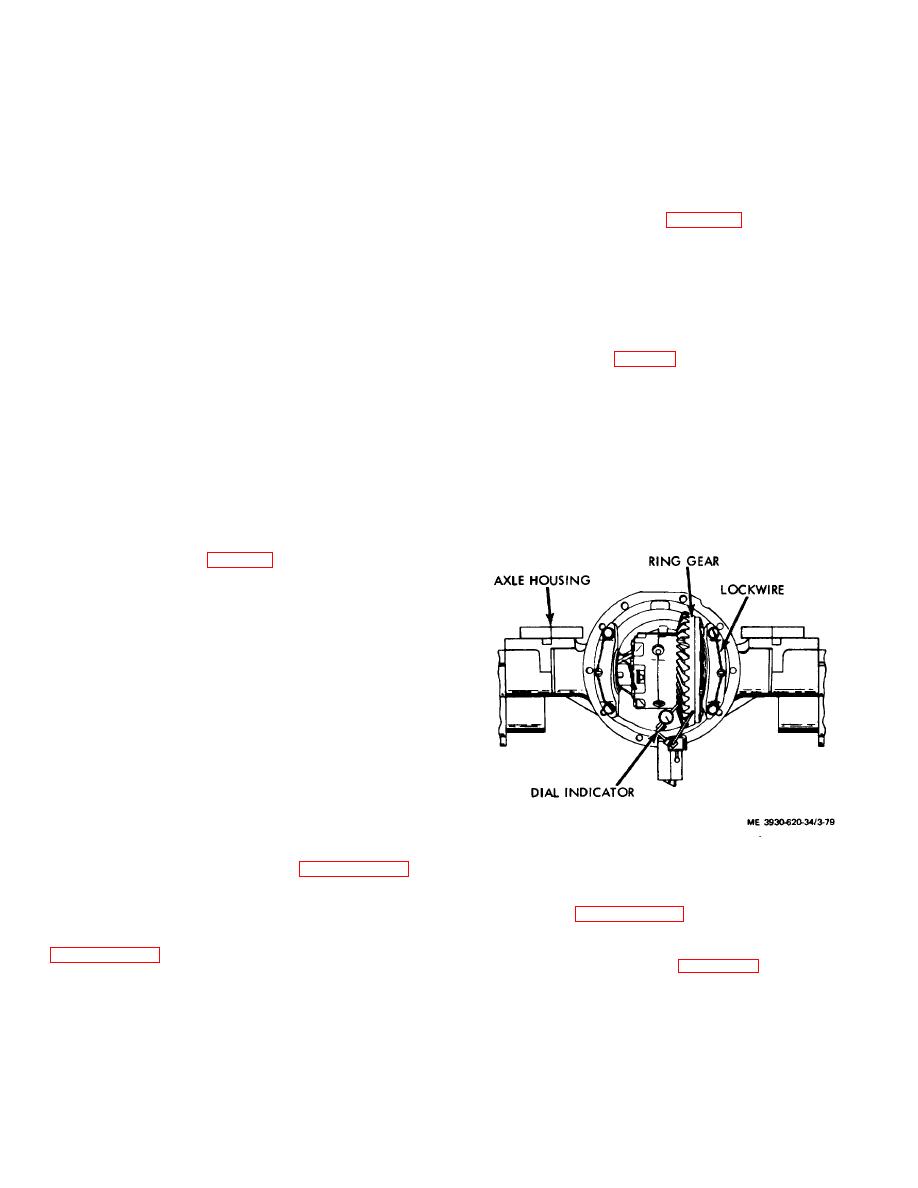
(8) Using a dial indicator, check ring gear laterally
(8) Position jackshaft assembly in drive unit
for 0.005 to 0.010 inch backlash.
housing.
(9) Check backlash at four positions (90 degrees
(9) Using a soft mallet, tap jackshaft into proper
apart on ring gear. (fig. 3-79.)
position.
Caution:
Whenadjusting
(10) Secure axle shaft cap to housing using screws.
backlash, rotate each adjusting nut
(11) Install dust shield and secure using screws.
exactly the same distance to maintain
(12) Install drive wheel assembly (TM 10-3930-620-
proper bearing preload.
12).
(10) Backlash is increased by removing lock,
3-45. Spindle
loosening adjusting nut nearest ring gear, and tightening
a. Removal, Cleaning, and Inspection.
opposite nut.
(1) Remove drive wheel assembly (TM 10-3930-
(11) Backlash is decreased by removing lock,
620-12).
loosening adjusting nut farthest from ring gear, and
(2) Remove dust shield.
tightening opposite nut.
(3) Remove cotter pin, lock nut and washer from
inboard end of spindle. (fig. 3-78.)
(4) Install spindle puller and remove spindle.
(5) Inspect spindle and bearings.
(6) If spindle and bearings are damaged, replace as
required.
b. Installation.
(1) Position spindle in drive wheel housing.
(2) Install washer and lock nut.
(3) Tighten lock nut until spindle is properly seated.
(4) Install cotter pin.
(5) Install bearings and dust shield.
(6) Install drive wheel assembly (TM 10-3930-620-
12).
3-46. Differential
a. General. Whenever it becomes necessary to
adjust differential carrier backlash, the drive unit may
remain installed or may be removed from the lift truck. If
Figure 3-79. Ring gear backlash being checked.
drive unit is to be removed from the lift truck to adjust
3-47. Drive Unit
differential carrier backlash, refer to paragraph 3-47 for
a. General. The drive axle housing and drive motor
disassembly procedures.
should be removed as an assembly to service the drive
b. Adjusting Backlash.
axle. Refer to paragraph 2-23 for removal and installation
(1) Position lift truck on level ground.
procedures.
(2) Remove mast assembly in accordance with
b. Disassembly of Axle Housing. Disassemble
according to the sequence of figure 3-80 and as follows:
(3) Drain differential housing oil. If oil is to be
reused, insure that oil is drained into a clean container.
3-91
|
|
Privacy Statement - Press Release - Copyright Information. - Contact Us |
