 |
|||
|
|
|||
|
Page Title:
Figure 3-70. Power steering cylinder, exploded view. |
|
||
| ||||||||||
|
|
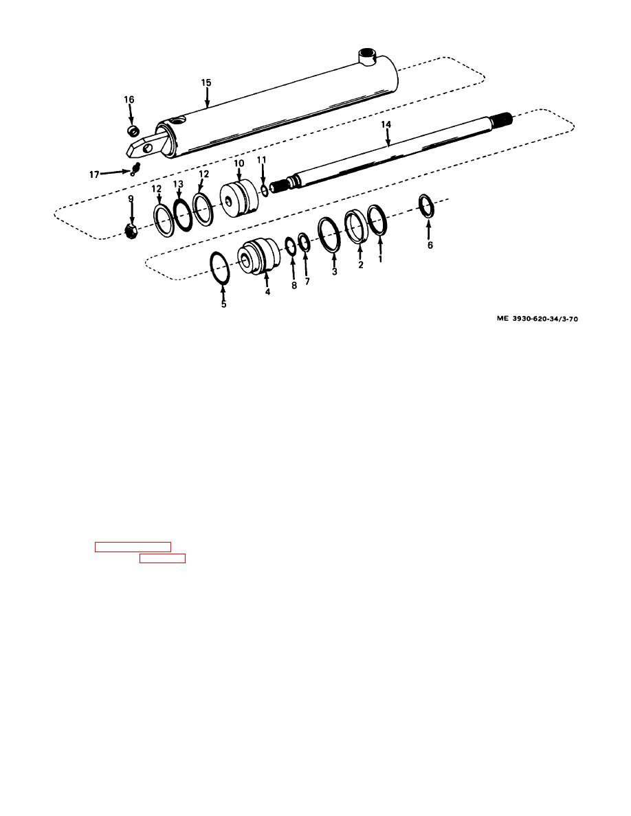 1. Lock ring
10. Piston
2. Spacer
11. Seal
3. Lock ring
12. Backup ring (2)
4. Head
13. Packing
75. Packing
14. Rod
6. Wiper ring
15. Cylinder
7. Backup ring
16. Bushing
8. Packing
17. Lubrication fitting
9. Nut
Figure 3-70. Power steering cylinder, exploded view.
(3) Remove stator from housing.
3-39. Power Steering Pump
(4) Remove retaining rings (15), drive gear
a. General. The power steering pump is used to
(13), and key (17) from drive shaft (10).
provide a constant supply of oil pressure to the power
(5) Remove drive shaft by pulling shaft
steering gear. A relief valve is incorporated in the pump
through gear housing.
to protect the power steering hydraulic system in the
(6) Pull idler shaft (12) from gear housing.
event of excessive hydraulic pressure.
(7) Remove retaining rings (16), gear (13),
b. Removal. Remove the power steering pump
and pin (14).
according to paragraph 2-12.
Note. Record number of
(1) Secure power steering pump in vise.
turns required to remove adjusting
(2) Remove screws (1) securing housing and
screw.
stator.
3-80
|
|
Privacy Statement - Press Release - Copyright Information. - Contact Us |
