 |
|||
|
|
|||
|
Page Title:
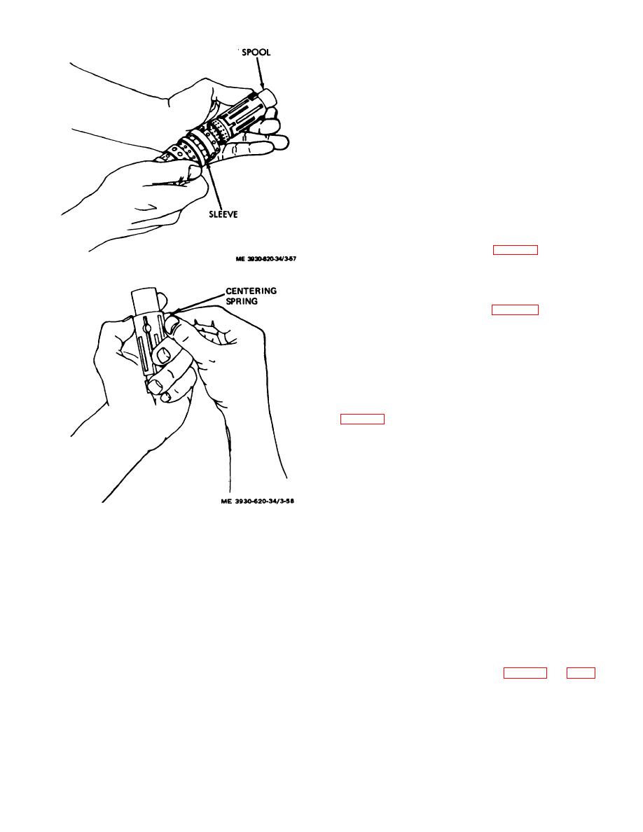
Figure 3-57. Spool removed from sleeve. |
|
||
| ||||||||||
|
|
 (d)
Inspect each part to insure that surfaces
are completely polished.
Warning: Use
an
approved
cleaning solvent.
Wear suitable
eye
protection
when
using
compressed air.
(e) Clean each part in an approved solvent
and dry using compressed air.
(f) each cleaned part in an area free of
contaminants and other foreign matter.
d. Reassembly
(1) Secure power steer gear housing in a
suitable vise with control end facing upward and 14-hole
end resting on a clean wooden block.
(2) Clamp vise jaws lightly across the port
face.
(3) Install check valve spring into check hole
with large end facing downward. (fig. 3-59.)
(4) Install check ball into check hole and
Figure 3-57. Spool removed from sleeve.
insure it rests on top of small end of spring.
(5) Place check valve seat on hex wrench and
install it in check valve hole so that machined
counterbore seats on check ball. (fig. 3-60.)
(6) Torque check valve seat to 150 inch-
pounds.
Note.
Check ball does not
have to be snugged against seat to
function properly.
(7) Test check ball action by pushing ball
against the spring force using a small clean pin.
(8) Carefully install spool within the sleeve.
(9) Insure that spring slots of both parts are
located at the same end.
(10) Carefully rotate spool while sliding parts
together.
Caution: Insure
that
spool
rotates smoothly in sleeve when
fingertip pressure is applied at
splined end.
Figure 3-58. Spring being removed from spool.
(11) Check spool for freedom of rotation.
(12) With spring slots of both parts aligned,
(b) Remove sharp grit from abrasive paper
position parts on end and insert spring installation tool
by cleaning ends of star gear.
through slots in both parts.
(c) both sides of ring gear, both sides
(13) Position 3 pairs of centering springs (or 2
of plate, the 14-hole end of housing, and flat surface
sets of three each) on work bench so that extended edge
of end cap by rubbing against abrasive paper.
is facing downward and arched center section is
(6) Polish surfaces of meter section as follows:
together.
Note.
When hand polishing,
(14) While holding this position, insert one end
hold parts firmly against abrasive
of entire spring set into spring installation tool.
surface.
(15) Compress extended end of centering
(a) Stroke each surface across abrasive
spring set and push it into spool and sleeve assembly
paper several times.
while withdrawing installation tool. (fig. 3-62 and 3-63.)
(b) Check for bright areas on the surface
(16) Insure that spring set is centered in the
which may indicate the presence of a burr.
parts so they can be pushed down evenly and flush with
(c) Remove burr' by stroking surface across
the upper surface of the spool and sleeve assembly.
abrasive paper six to ten times.
(17) Install centering pin through spool
assembly and push into place until centering pin is
3-75
|
|
Privacy Statement - Press Release - Copyright Information. - Contact Us |
