 |
|||
|
|
|||
|
Page Title:
Figure 3-46. Seat brake, exploded view. |
|
||
| ||||||||||
|
|
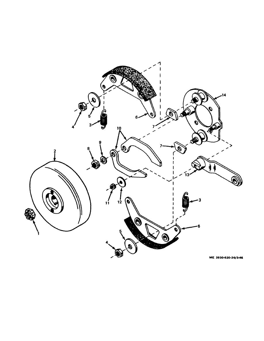 (2) If the seat brake and brake linkage are properly
tension block located along side of the seat hinge
adjusted, the seat brake will be applied when the
actuates the seat switch. The seat switch opens and
operator's seat is raised. The spring pressure which
interrupts power to the directional and power steering
applies the brake is removed when a weight (e.g. the
control circuits and all other systems. If the seat switch is
operator) is applied to the seat.
properly adjusted, the lift truck remains stationary when
(3) The same spring pressure that applies the seat
the operator's seat is raised (unoccupied). The systems
brake also raises the operator's seat (when unoccupied)
become operational when sufficient weight is applied to
through mechanical linkage. As the seat is raised, a
the operator's seat.
1. Slotted nut
8.
Nut
2. Drum
9.
Flat washer
3. Spring (2)
10.
Actuating arm (2)
4. Nut (2)
11.
Nut
5. Flat washer (2)
12.
Flat washer
6. Shoe (2)
13.
Actuating cam
7. Drive block (2)
14.
Backing plate
Figure 3-46. Seat brake, exploded view.
3-67
|
|
Privacy Statement - Press Release - Copyright Information. - Contact Us |
