 |
|||
|
|
|||
|
|
|||
| ||||||||||
|
|
 b. Inspection.
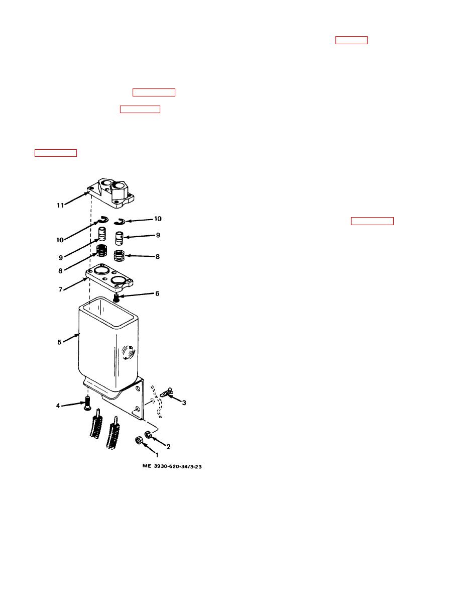
KEY to fig. 3-23:
(1) Inspect the shunt elements for damage,
overheating, and dirty contact surfaces.
1.
Nut (4)
(2) Inspect the standoff insulators for
2.
Lock washer (4)
cracking, dirt, and grease.
3.
Screw (4)
(3) Clean or replace parts as necessary.
c. Reassembly. Reassemble the shunt in the
4.
Screw (2)
5.
Body, mounting half
reverse order of that shown in figure 3-22. Insure that
6.
Screw (2)
cables and wires are reconnected correctly according to
7.
Contact block, outer
the tagging and as shown in figure 3-22.
8.
Contact spring (2)
3-15. Battery Connector
9.
Contact (2)
a. Removal. Remove the battery connector (TM
10.
Retaining ring (2)
10-3930-620-12).
11.
Contact block, inner
b. Disassembly. Disassemble connector as shown
in figure 3-23. Do not disassemble the contacts from the
c. Inspection.
Inspect all parts for wear,
cables unless necessary. If necessary, unsolder the
cleanliness, damage, and corrosion. Check springs for
contacts using an LP torch.
tension.
d. Repair. Replace any defective parts. Springs,
contacts, and retaining rings are replaced as a kit.
Contact blocks and screws are replaced as a kit.
e. Reassembly. Reassemble connector in the
reverse order of that shown in figure 3-23. Use an LP
torch and rosin core solder to connect contacts to cables.
Figure 3-23. Battery connector, exploded view.
3-36
|
|
Privacy Statement - Press Release - Copyright Information. - Contact Us |
