 |
|||
|
|
|||
|
Page Title:
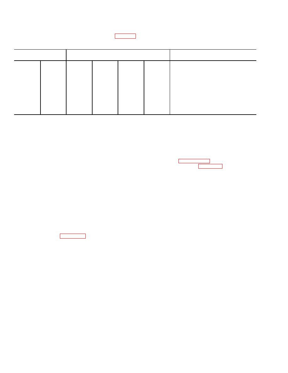
Table 3-1. Protective Circuit Voltage Tests |
|
||
| ||||||||||
|
|
 caution: For measurements with the
should read 2 to 2.5 volts, indicating the protective circuit
is not tripped. If the full battery voltage is read, the circuit
accelerator pedal down, proceed as
is tripped and must be reset before continuing.
rapidly as p1ossibltl to avoid burning out
(4) Make the voltage measurements of table 3-1
the 10 ohm resistor in the contactor unit.
Table 3-1. Protective Circuit Voltage Tests
Voltmeter lead
Select
Accelerator
Voltage
connection
direction
pedal
reading
Positive
Negative
(Red)
(Black)
Yes
No
Up
Down
B+
33
X
X
Full battery voltage
B+
34
X
X
Full battery voltage
B+
34
X
X
Less than 5 volts
31
B+
X
X
3 volts
B+
31
X
X*
5 volts
B+
36
X
X*
Full battery voltage
* Do not hold accelerator pedal In the down position These test should be accomplished as rapidly as possible
b. Trouble Analysis. If all of the voltages are
3-12. Directional Control Switch
correct, likely causes of trouble are as follows.
a. General. The directional control switch is a lever-
(1) Protective circuit trips when direction is
operated, double-pole, double-throw switch with a center
selected due to:
off position. Detents are provided to hold the switch in
(a) Defective control unit-low bias.
any of its three positions.
(b) Defective power switch-open emitter,
b. Removal. Remove the directional control switch
shorted base to collector.
according to paragraph 2-8.
(c) Improper turn-on sequence.
c
(2) Protective circuit trips when pedal is
(1) Squeeze contact finger assemblies (6)
depressed only far enough to operate microswitch due
together, rotate 1/2 turn, and withdraw assemblies and
to:
contact finger spring (7).
(a) Open or intermittent 10 ohm resistor in
(2) Remove screws through terminal board
contactor unit.
assemblies (8 and 9) and remove assemblies.
(b) Shorted power switch.
(3) Unhook handle springs (10) from pins and
(3) Protective circuit trips when
pedal is
remove.
depressed far enough to generate a drive signal due to:
(4) Remove screws holding clips (11 ) and
(a) Defective control unit-low drive.
remove clips and arms.
(b) Open, intermittent, or wrong value in
(5) Remove screw and washers holding carrier
assembly and remove assembly.
resistor assembly.
c. Removal. Tag and disconnect the leads and
(6) Remove operating shaft assembly (15),
washer (16), and spacer (17).
remove according to figure 3-13.
d. Cleaning.
d. Installation. Install the protective circuit according
(1) Blow dust from parts with compressed air
to the reverse of removal.
under moderate pressure.
3-32
|
|
Privacy Statement - Press Release - Copyright Information. - Contact Us |
