 |
|||
|
|
|||
|
Page Title:
Figure 3-18. Transistor terminal identification |
|
||
| ||||||||||
|
|
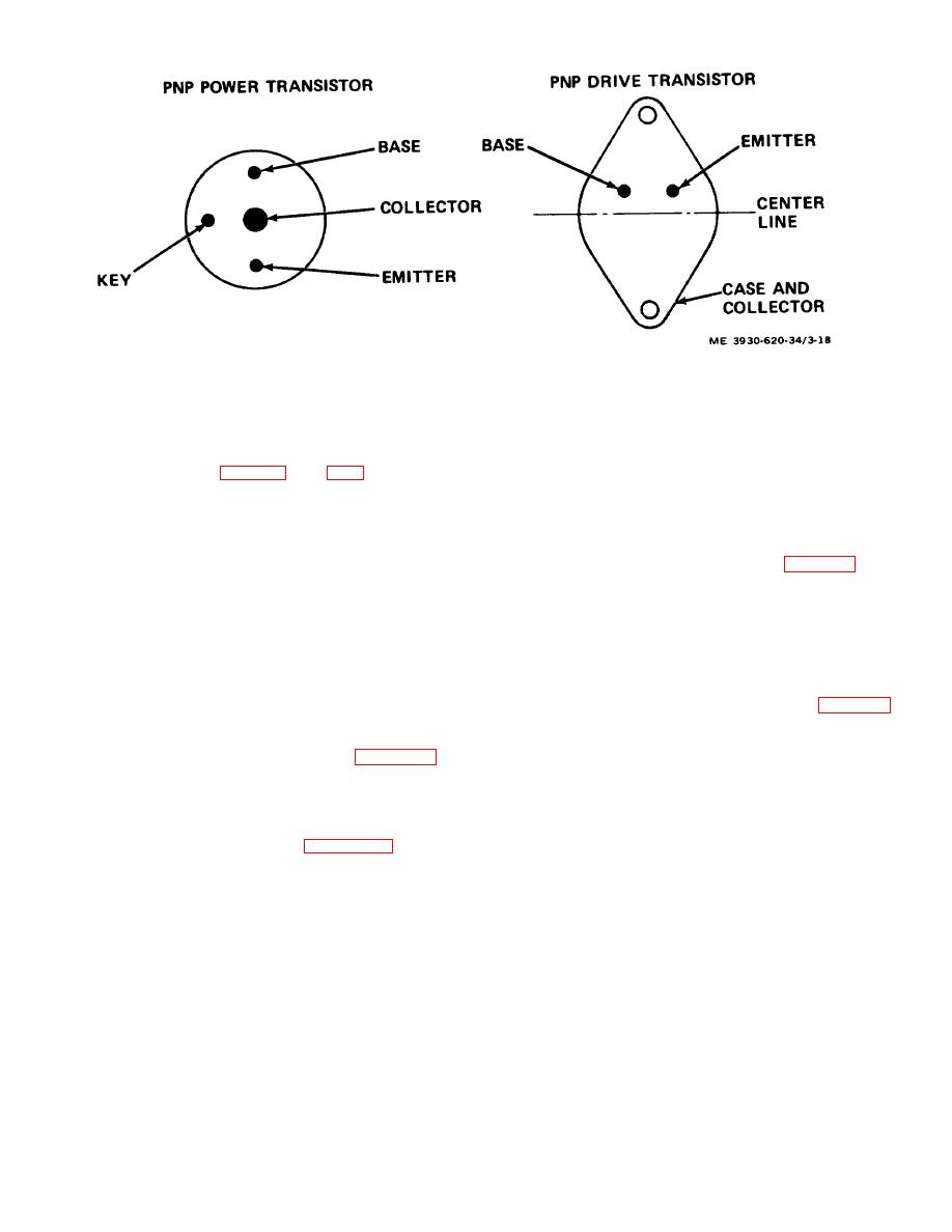 Figure 3-18. Transistor terminal identification
identification.
(2) To determine transistor leakage, check on a
(e) Reconnect encapsulated resistors on
transistor checker.
h. Diode Bias Block Test. Check each diode in the
collector bus bar and emitter leads on emitter bus bar
diode bias block for forward and backward resistance
(28).
(f) Reconnect all electrical leads and
resistance must be about 10 times higher than forward
check for possible wiring errors.
resistance.
3-10. Capacitor and Diode Assembly
i. Inspection of parts.
a. Inspection.
(1) Inspect all parts for general condition and
(1) Inspect the capacitor and diode assembly for
signs of overheating and oxidation.
dust, dirt, and other foreign material. (fig. 3-14.) Pay
(2) Check electrical leads for frayed or
particular attention to the areas between the fins of the
deteriorated condition.
heat sinks.
(3) Check printed wiring board for cracks or
(2) Check for any evidence of damage such as
other damage. If in doubt, check printed wiring for
capacitor leakage, overheating, and arcing.
b. Test. Test the capacitor and diode assembly
(4) Measure board mounted resistors and
using an ohmmeter. Disconnect battery and discharge
encapsulated resistors using an ohmmeter and milliohm
capacitors (para2-5I. Tag and disconnect all leads
meter.
coming to terminals Al, A2, B2-, and B2+. (fig. 3-19.)
j. Reassembly.
Reconnect the leads after the test.
(1) Reassemble an individual power switch
(1) Measure forward resistance of diode D 1 by
module in the reverse of the order shown in figure 3-17.
connecting ohmmeter between terminals Al (-lead) and
Note. Use silicone grease between the
B2- (+lead). Note reading.
transistors and their heat sinks when
(2) Measure D1 backward resistance by
assembling.
reversing
the
connections.
Backward-to-forward
(2) Reassemble the power switch assembly in
resistance ratio should be at least 10 to 1.
the reverse of the order shown in figure 3-15, and as
(3) Measure forward resistance of diode D2 by
follow s.
connecting ohmmeter between terminals Al (-lead) and
(a) Assemble power switch modules on
A2 (+ lead). Note reading.
mounting rods 147) between end plates.
Position
(4) Measure D2 backward resistance by
spacers (44) between power switch modules.
reversing
the
connections.
Backward-to-forward
(b) Tighten nuts (42) at both ends of
resistance ratio should be at least 10 to 1.
insulated mounting rods.
(5) Disconnect the D3 lead from the capacitors.
(c) Position collector bus bar (27) under
(6) Measure forward resistance of diode D3 by
encapsulated resistors (33) and on top of modules.
connecting ohmmeter between terminal Al (- lead) and
(d) Align holes in collector bus bar and
the D3 lead (+ lead). Note reading.
install and tighten attaching hardware terminal
3-29
|
|
Privacy Statement - Press Release - Copyright Information. - Contact Us |
