 |
|||
|
|
|||
|
Page Title:
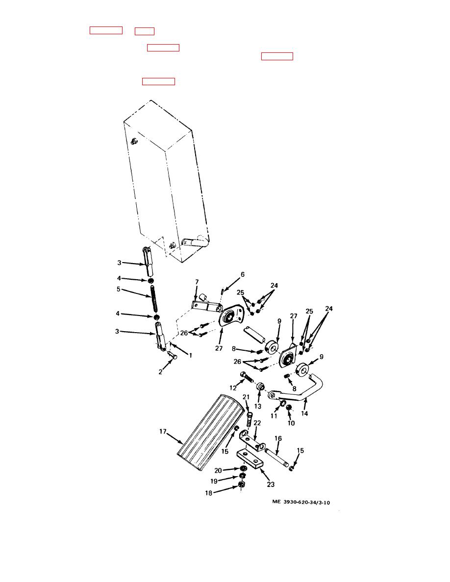
Figure 3-10. Accelerator pedal and linkage, exploded view |
|
||
| ||||||||||
|
|
 c.
Inspection. (fig. 3-10 and 3-11.)
for freedom of movement and that the pedal returns to
the up position.
(1) Remove toe plate ITM 10-3930-620-12}.
(4) To check spring tension, remove the cotter
(2) Remove the two nuts (1, fig. 3-11) and lock
pin (1, fig. 3-10) and yoke pin (2) to separate the yoke
washers (2) and remove the cover (3) and gasket 141
(3) from the box assembly shaft. A force of 17 to 25
from the speed control box assembly. Inspect the
pounds should be required to move the shaft. Reconnect
gasket for damage and deterioration.
the yoke and shaft.
(3) Operate the pedal ( 17, fig. 3-10) and check
Figure 3-10. Accelerator pedal and linkage, exploded view
3-18
|
|
Privacy Statement - Press Release - Copyright Information. - Contact Us |
