 |
|||
|
|
|||
|
Page Title:
Figure 3-4. Diode bridge block connection |
|
||
| ||||||||||
|
|
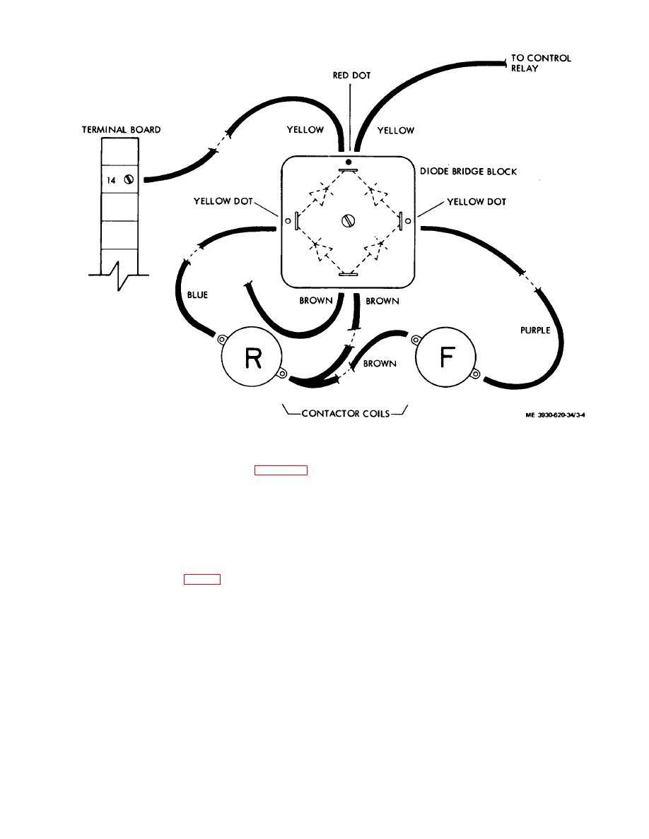 Figure 3-4. Diode bridge block connection
e. Pump or Emergency Cutout Contactor.
(2) Inspect parts for wear and damage,
including contacts (3).
(1) Disassemble in the sequence of figure 3-5
(3) Reassemble in the reverse order of
and as follows:
(a) Disconnect flexible lead (8).
disassembly.
(4) Check for maximum air gap of 5/ 16 inch.
(b) Remove
armature
screws
(5) Check for maximum contact misalignment
allowing complete armature
(16) to be removed.
when closed of 3/64
inch.
(c) Lift return spring (18) out of coil center.
Insert screw driver down center of coil and remove coil
mounting screw (1) and lock washer (20).
KEY to fig. 3-5:
18.
Return spring
19.
Screw
1.
Screw (2)
20.
Lock washer
2.
Lock washer (2)
21.
Magnet coil
3.
Contact (2)
22.
Core
4.
Screw
23.
Screw (2)
5.
Screw
24.
Lock washer (2)
6.
Lock washer
25.
Armature retainer
7.
Washer
26.
Screw
8.
Flexible lead
27.
Washer
9.
Cotter pin
28.
Armature retainer support
10.
Cup washer
29.
Screw
11.
Centering washer
30.
Washer
12.
Contact spring
31.
Stationary contact support
13.
Movable carrier
32.
Screw
14.
Pivot bearing
33.
Countersink lock washer
15.
Shoulder pin
34.
Stationary contact block
16.
Armature
35.
Magnet yoke
17.
Stop pivot
3-8
|
|
Privacy Statement - Press Release - Copyright Information. - Contact Us |
