 |
|||
|
|
|||
|
|
|||
| ||||||||||
|
|
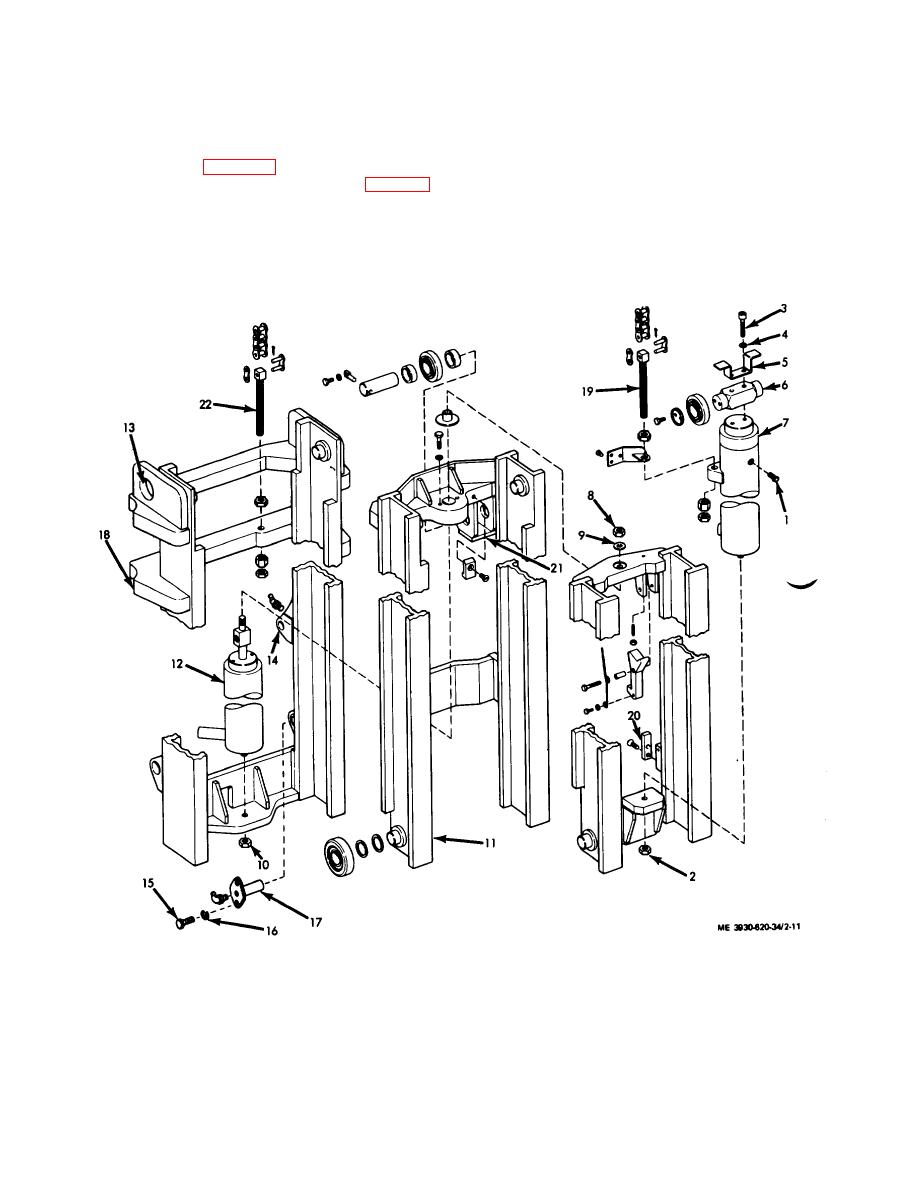 c. Installation. Install the carriage and backrest
(5) Disconnect hydraulic lines to the cylinder.
Cap or plug openings.
assembly in the reverse order of removal.
(6) Remove the nut (2) securing the lower end
2-17. Primary Lift Cylinder
of the cylinder to the mast assembly.
a. Removal.
(7) Remove the screws (3) and washers (4)
(1) Lower the fork carriage and remove the
securing the upper end and take off the guard (5) and
carriage and backrest (para 2-16).
crosshead (6).
(2) Free the end of the cylinder (7, fig. 2-11)
Caution: Be careful not to damage the
of its lift chains (TM 10-3930-624-12).
(3) Remove the bleed screw (1) and insert a
cylinder when removing it from the mast assembly.
high pressure air hose. With the lift control lever held in
(8) Attach a chain securely around the outer
the DOWN position, blow the oil out of the cylinder back
case of the cylinder below the chain bolt flanges and
into the reservoir.
remove the cylinder.
(4) Disconnect the high pressure hose.
1.
Bleed screw
7. Primary lift cylinder
12.
Secondary lift cylinder
17.
Pivot pin (2)
2.
Nut
8. Nut
13.
Lifting eye (2)
18.
Outer mast
3.
Screw 121
9. Washer
14.
Tilt cylinder mast bracket (2)
19.
Chain adjustment bolt l2'
4.
Washer 12)
10. Nut
15.
Screw (4)
20.
Stop
5.
Guard
11. Intermediate mast
16.
Lock washer 14)
21.
Crosshead support
6.
Crosshead
22.
Chain adjustment bolt (2)
Figure 2-11. Mast assembly.
2-14
|
|
Privacy Statement - Press Release - Copyright Information. - Contact Us |
