 |
|||
|
|
|||
|
Page Title:
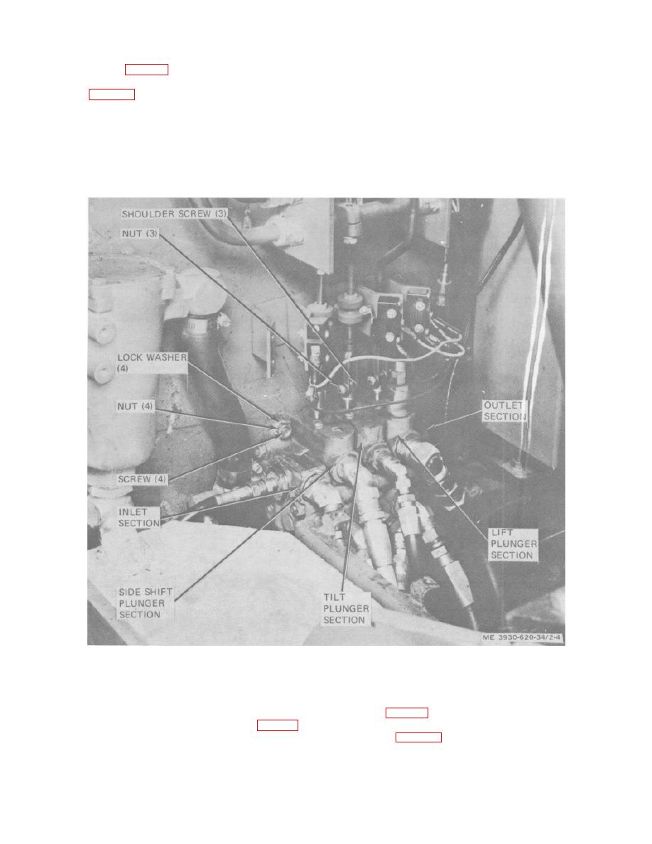
Figure 2-4. Control valve removal and installation. |
|
||
| ||||||||||
|
|
 (5) Plug ends of hydraulic lines to prevent
2-9. Control Valve
entry of foreign matter.
(6) Remove the three shoulder screws and
(1) Disconnect
battery
and
discharge
nuts to disconnect yokes from control valve plungers.
capacitors (para 2-5).
(7) Remove the four control valve mounting
(2) Remove control valve cover panel to gain
screws, lock washers and nuts.
access to control valve and connections (TM 10-3930-
(8) Remove control valve from lift truck.
620-12).
Warning: Use an approved cleaning
(3) Identify and tag each hydraulic line
according to where it connects.
solvent.
(4) Disconnect hydraulic lines from control
(9) Clean exterior of control valve using an
valve.
approved solvent.
Figure 2-4. Control valve removal and installation.
b. Installation.
(4) Check adjustments described in c, below,
c. Adjustment.
(1) Install control valve on lift truck center
(1) Adjust lift plunger section relief valve as
plate.
follows. (fig. 2-5.)
(2) Unplug all control valve openings and
(a) Disconnect battery and discharge
reconnect hydraulic lines to appropriate ports. (fig. 2-4).
(3) Connect yokes to control valve plungers.
capacitors (para 2-5).
removal and installation.
2-7
|
|
Privacy Statement - Press Release - Copyright Information. - Contact Us |
