 |
|||
|
|
|||
|
Page Title:
Section II. REPAIR OF BRAKE SYSTEM |
|
||
| ||||||||||
|
|
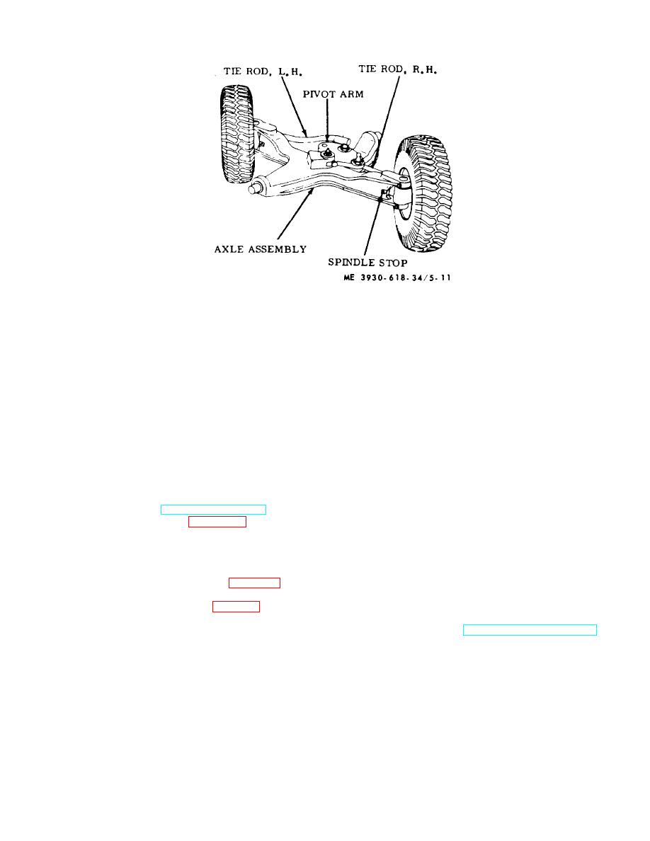 Figure 5-11. Stop adjustment.
Section II. REPAIR OF BRAKE SYSTEM
(7) Remove screws (3) and lockwashers (2)
5-11. General
and remove backing plate (1) from pinion bearing cap.
The handbrake is a dual-shoe, mechanical-type and is
mounted to the differential pinion flange.
The
b. Inspection.
brakeshoes are actuated through a cable by an
(1) Check backing plate for distortion, loose or
adjustable, over-center type lever. The service brake
sheared rivets, and worn pawls.
system contains a mechanically actuated hydraulic
(2) Check brake lining for abnormal wear or
master cylinder with an attached power booster. A heavy
grease saturation.
duty brake line transmits hydraulic pressure from the
(3) Check brakeshoes for worn pawl holes,
power booster to double-end type cylinders in each drive
lever contact areas or wear pads and cracks or
wheel. The brakeshoes are the free floating type, and
distortion.
are provided with major and minor adjustment cams,
(4) Check brakedrum for cracks, scoring, or
accessible at the rear of the backing plates.
other damage.
5-12. Handbrake Assembly
(5) Replace drum if defective. If serviceable,
a. Removal. Refer to TM 10-3930-618-20.
use fine emery cloth to remove discolorations and lining
b. Disassembly. Refer to figure 5-12 and proceed
residue from interior surfaces.
as follows:
(6) Replace other defective parts as
(1) Remove universal joint.
authorized.
(2) Detach lower cable yoke from actuating
c. Reassembly and Installation.
lever (5).
(1) Reverse procedures in a above.
(3) Remove cotter pin (37, fig. 5-19) and
(2) Apply light coat of brake lubricant to wear
remove nut (38) from drive pinion shaft.
pads and pawls on backing plate and wear surfaces of
(4) Remove brakedrum (8, fig. 5-12).
actuating lever and shoes.
(5) Remove springs (7) from brakeshoe
(3) Refer to TM 10-3930-618-20 for
assemblies (6) and slide shoes from actuating pawls.
adjustment.
(6) Remove actuating lever (5) and rollers (4).
5-16
|
|
Privacy Statement - Press Release - Copyright Information. - Contact Us |
