 |
|||
|
|
|||
|
|
|||
| ||||||||||
|
|
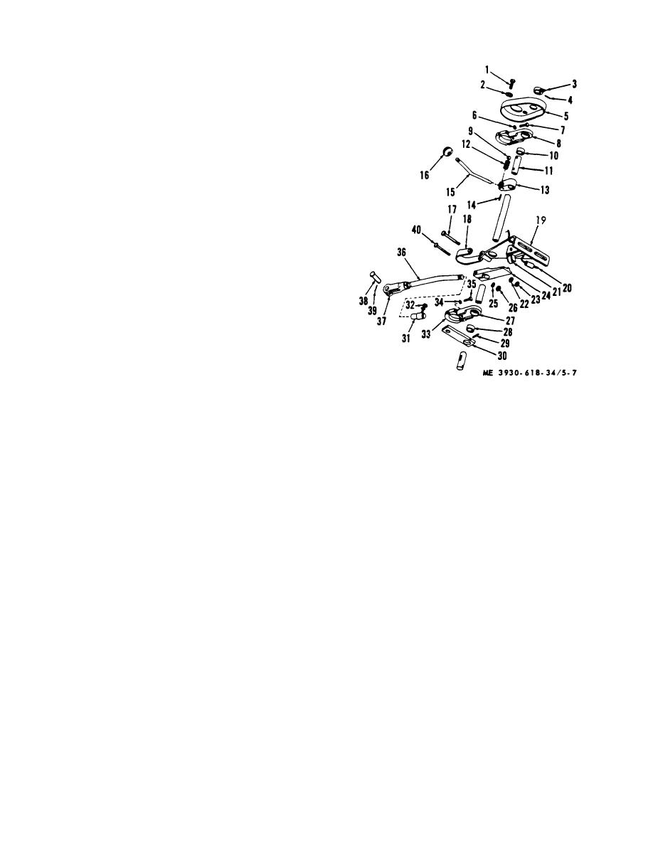 (5) Loosen actuating lever capscrew (40).
(6) Detach shifting rod ball joint (31) from shift
lever (30).
(7) Lift mechanism out of truck.
(8) Shift lever can now be removed by
removing pin (29).
b. Cleaning and Inspection.
(1) Clean all parts in SD and dry.
(2) Inspect all parts for excess wear,
deformation, cracks, stripped threads, and other
damage.
(3) Replace defective parts as authorized.
c. Installation. Install in reverse order of removal.
d. Adjustment.
(1) If shifting mechanism binds, check
alignment at mounting bracket (8) on steering column
and mounting bracket (27).
(2) To obtain proper operation of the shifting
mechanism it is important that the detent in the indicator
plate be synchronized with the detents in the selector
valve plunger. Correct synchronization of the detents
can be obtained by adjusting the rod assembly (36)
between the selector valve plunger and the lever (30).
(3) After shifting detents are correctly
adjusted, the neutral switch (21) and lever (24) should be
adjusted for correct operation.
(4) To adjust, loosen capscrew (40) holding
lever (24) to shifting rod (11) and, with the shifting
mechanism in neutral, move cam so that switch lever is
1 Screw
21 Switch
at lowest point on cam, making sure switch is in OFF
2 Lockwasher
22 Lockwasher
position.
3 Indicator
23 Nut
(5) Tighten capscrew in switch lever. Move
4 Pin
24 Lever
shifting lever (15) to either forward or reverse position,
5 Cover
25 Lockwasher
turn ignition key to start. If engine does not start,
6 Lockwasher
26 Nut
adjustment is correctly made.
7 Screw
27 Bracket assembly
8 Bracket
28 Bushing
9 Ball
29 Pin
10 Bushing
30 Lever
11 Rod
31 Joint
12 Spring
32 Nut
13 Stop
33 Bracket assembly
14 Pin
34 Washer
15 Shifting lever
35 Screw
16 Knob
36 Rod
17 Screw
37 Yoke
18 Clip
38 Pin
19 Support assembly
39 Cotter pin
20 Wire
40 Screw
Figure 5-7. Forward-reverse assembly.
5-9
|
|
Privacy Statement - Press Release - Copyright Information. - Contact Us |
