 |
|||
|
|
|||
|
Page Title:
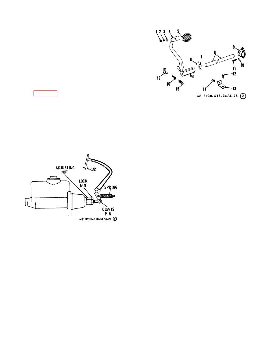
Figure 3-28. Brake pedal (sheet 1 of 2) |
|
||
| ||||||||||
|
|
 CAUTION
Do not attempt to stop the pedal
travel with the valve plunger rod
alone.
(4) If the valve plunger rod (4) bottoms before
the pedal (9) is fully released, and resting on its stop,
turn the pedal stop adjusting screw (14) in or out until
correct adjustment is obtained.
f. Service Brake Pedal Adjustment. The ideal
pedal free play is h inch. Too little free travel will prevent
the master cylinder piston from returning to full OFF
position and the brakes will begin to drag after several
applications. Excessive free travel will reduce the usable
stroke of the master cylinder.
Refer to figure 3-28 and adjust as follows:
(1) Remove the floor plates.
(2) Slowly depress the brake pedal and check
for 1/2 inch free travel. Also observe push rod action.
(3) To obtain the proper free travel, loosen the
locknut on the clevis and then turn the adjusting nut.
1 Nut
10 Loekwasher
(4) Tighten the locknut and reinstall the floor
2 Lockwasher
11 Capicrew
plates.
3 Washer
12 Capscrew
4 Pedal
13 Bracket
5 Pedal pad
14 Bumper
6 Pin
15 Spring
7 Washer
16 Adjusting screw
8 Pivot shaft
17 Clip
9 Support bearing
Figure 3-28. Brake pedal (sheet 2 of 2).
Figure 3-28. Brake pedal (sheet 1 of 2)
3-33
|
|
Privacy Statement - Press Release - Copyright Information. - Contact Us |
