 |
|||
|
|
|||
|
Page Title:
Figure 3-25. Reverse gear and shaft, removal and installation. |
|
||
| ||||||||||
|
|
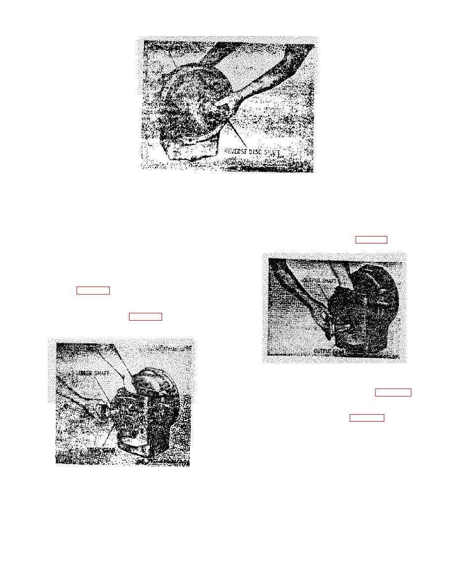 Figure 3-25. Reverse gear and shaft, removal and installation.
(f) Remove hearing (6) with retaining
(b) Remove retainer (31) by removing
ring.
attaching bolts (33) and lockwashers (32). Discard
(7) Idler gear shaft.
gasket (30).
(c) While holding output gear (28) in
(a) Remove retainer (23) by removing
gear box, remove output shaft (29) (fig. 3-27).
attaching bolts (24) and lockwashers (25). Discard
gasket (21).
(b) Mark position of pin (22) holding
shaft in retainer (23) to insure proper assembly and
remove pin.
(c) Remove idler shaft (20) and idler
gear assembly (fig. 3-26).
NOTE
Idler gear assembly consists of two
needle bearings (19, fig. 3-24) and a
gear (18).
Figure 3-27. Output gear and shaft, removal and
installation.
(d) Remove gear (28, fig. 3-24) and
both ball bearings (27).
(e) Remove expansion plug (26).
(9) Remove plug (41, fig. 3-24), spring (40),
and screen (39), from bottom portion of transmission
case (37).
b. Cleaning, Inspection, and Repair. Assure that
none of the dirt or sludge contains abrasive matter (metal
filings). If it has metal particles investigate possible
source of wear, or failure that caused accumulation.
Figure 3-26. Idler gear shaft, removal and installation.
Replace defective part or parts, then use extreme care in
cleaning the components.
(8) Output gear and shaft.
(a) Remove output flange (34) and oil
seal (35).
3-30
|
|
Privacy Statement - Press Release - Copyright Information. - Contact Us |
