 |
|||
|
|
|||
|
Page Title:
Figure 3-22. Forward reverse disc assembly. |
|
||
| ||||||||||
|
|
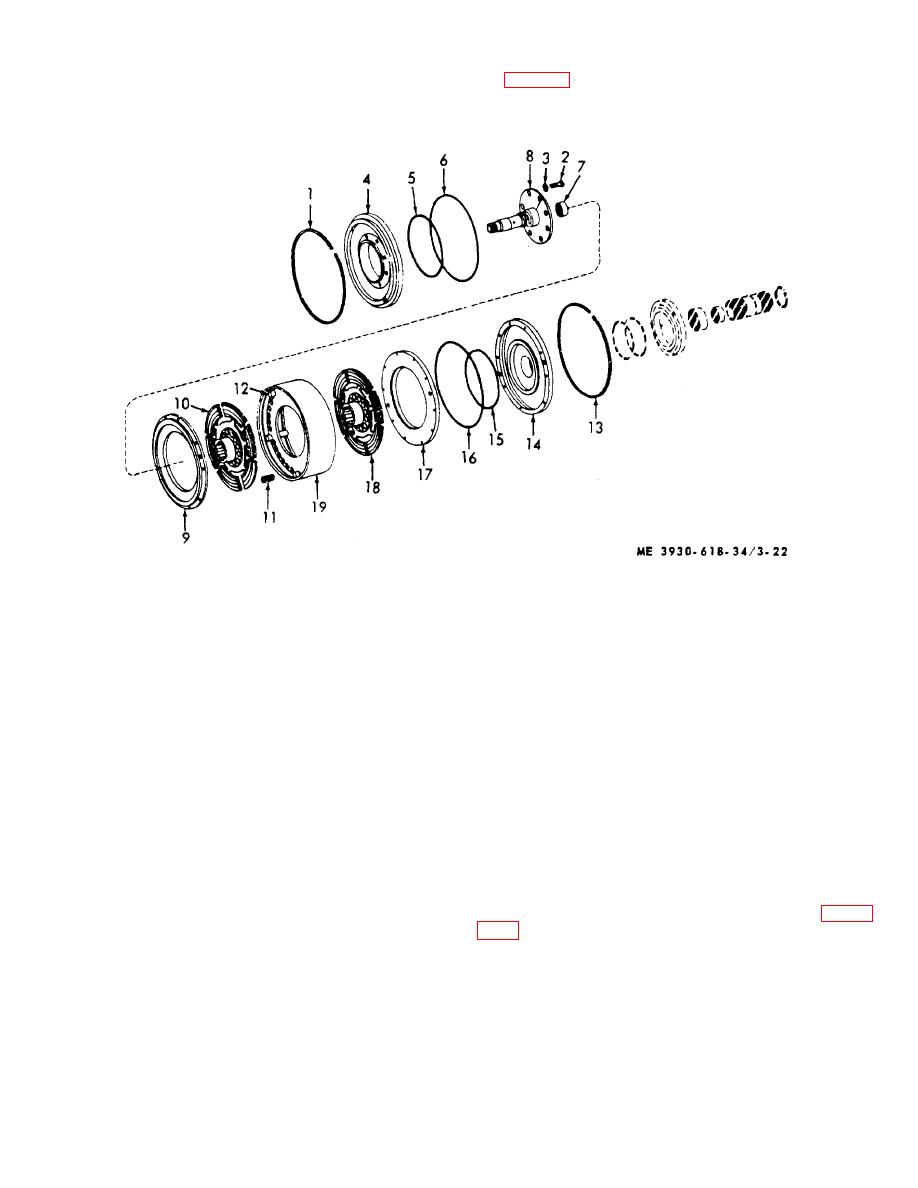 (a) Place drum and disc assembly in
cylinder is depressed enough to remove large snapring
(1, fig. 3-22).
arbor press.
Apply pressure on turbine shaft until
1 Snap ring
11 Spring
2 Capscrew
12 Pin
3 Lockwasher
13 Snap ring
4 Cylinder
14 Cylinder
5 Seal ring
15 Seal ring
6 Seal ring
16 Seal ring
7 Needle bearing
17 Piston
8 Turbine shaft
18 Disc
9 Piston
19 Drum
10 Disc
Figure 3-22. Forward reverse disc assembly.
(b) Remove the capscrews (2) and
(4) Transmission control valve.
(a) Remove
bolts
and
washers
lockwashers (3) and remove the cylinder (4) from the
turbine shaft (8). Remove seal rings (5 and 6). Remove
attaching transmission control valve to transmission
the needle bearing (7) from the turbine shaft (8).
case.
(c) Remove the piston (9), forward drive
(b) Clean valve exterior with cleaning
disc 10), spring (11) and pins (12) from the drum.
compound, solvent (Spec. P-S-661). Dry thoroughly
(d) Remove snap ring (13), cylinder (14), seal
with compressed air.
(c) Remove valve cover bolts (1, fig. 3-
rings (15 and 16), piston (17) and reverse disc (18) from
drum (19).
(28). Discard gasket.
3-26
|
|
Privacy Statement - Press Release - Copyright Information. - Contact Us |
