 |
|||
|
|
|||
|
|
|||
| ||||||||||
|
|
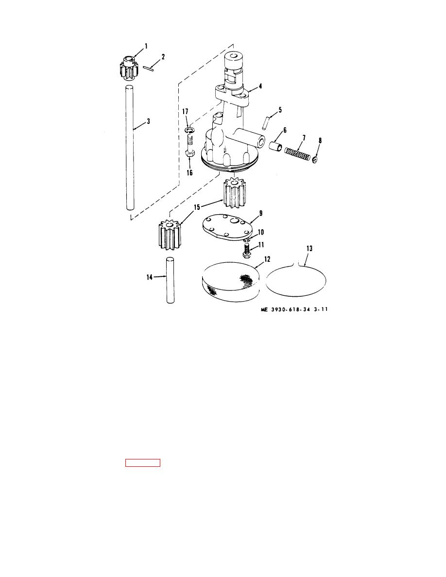 1 Drive gear
10 Lockwasher
2 Pin
11 Capscrew
3 Drive shaft
12 Screen
4 Body
13 Lockwire
5 Roll pin
14 Idler shaft
6 Valve piston
15 Pump gears
Valve spring
16 Capscrew
8 Spring retainer
17 Lockwasher
9 Cover
Figure 3-11. Oil pump.
oil pressure can be attributed to pump. To disassemble
NOTE
pump, proceed as follows:
If both oil pump and distributor are
(1) Remove suction screen retainer wire (13)
removed, as at engine overhaul. refer
and remove screen (12).
to g below for installation procedure.
(2) Remove capscrews (11) and lockwashers
(2) Remove oil pan (para 3-12).
(10) securing pump cover (9) to pump body (4), and
(3) Remove the two capscrews (16) and
remove cover.
lockwashers (17) which secure oil pump to cylinder
(3) Remove pump gears (15) and idler shaft
block. Withdraw pump from cylinder block.
(14) from pump body.
c. Disassembly.
Disassembly of oil pump
(4) Place pump assembly in position on a
advisable whenever the engine is overhauled or drop in
press
3-17
|
|
Privacy Statement - Press Release - Copyright Information. - Contact Us |
