 |
|||
|
|
|||
|
Page Title:
Figure 3-8. Governor disassembly. |
|
||
| ||||||||||
|
|
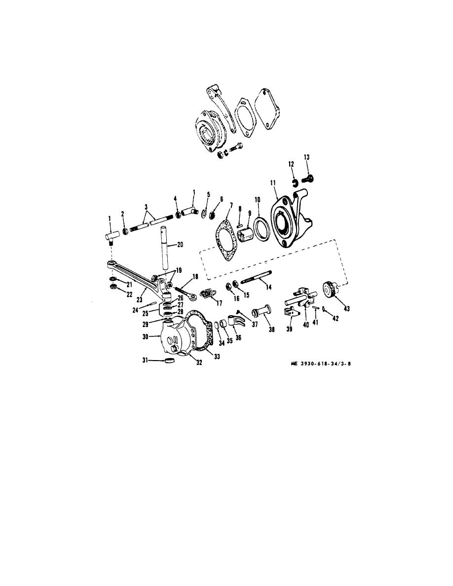 f. Installation.
(2) Install the throttle control rod on the
throttle lever.
(1) Install the governor on the engine by a direct
reversal of the procedures in b above. Be sure to use
(3) After installation, refer to TM 10-3930-
618-20 for adjustment instructions.
new gasket.
1 Ball joint
16 Nut
30 Body
2 Nut
17 Spring
31 Bushing
3 Control rod
18 Adjusting screw
32 Washer, copper
4 Nut
19 Nut
33 Gasket
5 Lockwasher
20 Shaft
34 Disc
6 Nut
21 Lockwasher
35 Bushing
7 Gasket
22 Nut
36 Yoke
8 Dowel pin
23 Throttle lever
37 Fastener
9 Bearing
24 Roll pin
38 Sleeve and bearing assembly
10 Thrust washer
25 Seal and retainer kit
39 Weight
11 Adapter assembly
26 Seal
40 Spider and shaft assembly
12 Lockwasher
27 Retainer
41 Pin
13 Capscrew
28 Bearing
42 Clip
14 Shaft
29 Snapring
43 Drive gear
15 Nut
Figure 3-8. Governor disassembly.
3-13
|
|
Privacy Statement - Press Release - Copyright Information. - Contact Us |
